
Lock torsional fatigue testing machine

A technology of torsional fatigue and testing machine, which is applied in the direction of strength characteristics, application of repeated force/pulsation force to test material strength, instruments, etc. It can solve the problems of wasting time, low test efficiency, and inability to detect multiple locks at the same time, and achieve enhanced Accuracy, the effect of ensuring normal operation

Active Publication Date: 2021-01-22
温州市龙湾海伦五金厂
View PDF9 Cites 0 Cited by
  • Summary
  • Abstract
  • Description
  • Claims
  • Application Information

AI Technical Summary

Problems solved by technology

[0004] The test efficiency is high. At present, the torsional fatigue degree of the lock is tested, mainly through the rotation of the motor to simulate the twist of the handle, to test the number of twists to detect the service life of the lock body in the lock, but it is not possible to simultaneously test multiple locks at the same time. For example: in a lock manufacturing factory, it is time-consuming to test new locks individually, and the test efficiency is low. If the torsion test can be performed on multiple locks at the same time, the test efficiency can be greatly improved; the test accuracy is higher. , through the counter, accurately count the number of twists, for example: the handle of the lock is twisted once and the counter is touched once, so as to count once, thereby improving the accuracy of the test

Method used


Image

  • Lock torsional fatigue testing machine
  • Lock torsional fatigue testing machine
  • Lock torsional fatigue testing machine

Examples


Embodiment

[0033] as attached figure 1 to attach Figure 8 Shown:

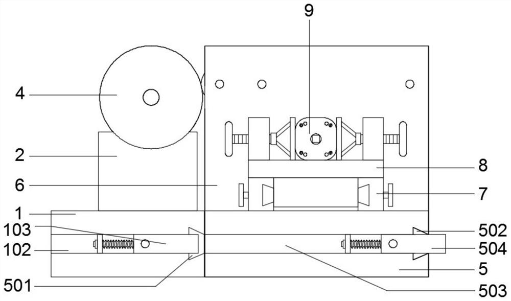
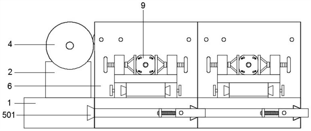
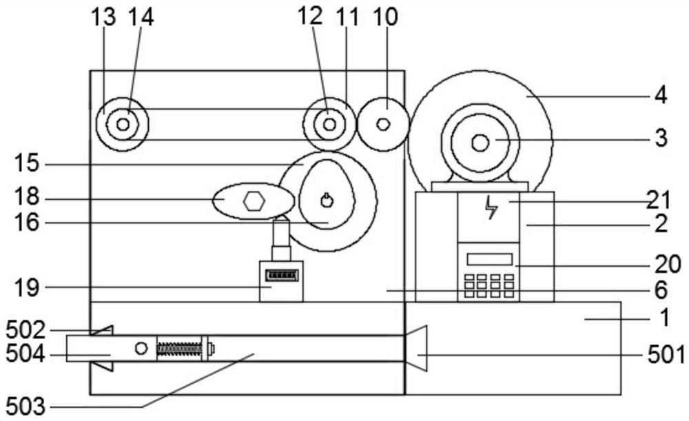
[0034]The invention provides a lock torsion fatigue testing machine, including: a rectangular seat A1, a trapezoidal groove A101, a rectangular groove A102, an elastic card A103, a motor seat 2, a motor 3, a gear A4, a rectangular seat B5, a trapezoidal clamping iron 501, and a trapezoidal groove B502, rectangular groove B503, elastic card B504, rectangular plate 6, sliding track 7, fixture structure 8, lock body body 9, gear B10, gear C11, pulley A12, gear D13, pulley B14, gear E15, cam 16, Cylindrical shaft 17, toggle plate 18, press counter 19, rolling ball 1901, governor 20, power control box 21 and main body of the detection structure; a trapezoidal groove A101 is opened on the right end of the rectangular seat A1, and the front end of the rectangular seat A1 A rectangular groove A102 is provided on the rear end surface, and an elastic card A103 is arranged in each rectangular groove A102; a motor seat 2 is welde...


PUM


Abstract

The invention provides a lockset torsion fatigue tester, which comprises a rectangular seat A, a power control box and detection structure main bodies. The top end face of a motor seat is fixedly connected with a motor, and the motor is electrically connected with a speed governor. Through matched arrangement of trapezoidal clamping iron, a trapezoidal groove B, an elastic clamping piece B, a gearB, a belt wheel A, a gear D and a belt wheel B, firstly, through the trapezoidal clamping iron, the trapezoidal groove B and the elastic clamping piece B, rectangular seats B of the two sets of detection structure main bodies can be connected and fixed; secondly, when the rectangular seats B of the two sets of detection structure main bodies are connected and fixed, the gear D on the first set ofdetection structure main body is engaged with the gear B on the second set of detection structure main body, and thus the second set of detection structure main body can be driven to operate; and thirdly, the belt wheel A and the belt wheel B are connected in a sleeving mode through a belt, thus the belt wheel A and the belt wheel B can be enabled to rotate in the same direction, and normal operation of the second set of detection structure main body is guaranteed.

Description

technical field [0001] The invention belongs to the technical field of lock detection equipment, and more specifically relates to a lock torsional fatigue testing machine. Background technique [0002] Locks are widely used in daily life, especially locks on indoor and outdoor doors. Existing locks are mainly composed of panels, handles, lock bodies, lock cores, keys, etc.; existing lock torsion detection equipment mainly detects the lock core, but the lock body also has a service life. Connected with the lock body, when the key is not used to lock the lock cylinder, usually we turn the handle to drive the internal parts of the lock body to open and close the door, but the lock body also has a service life, when the lock body reaches the service life When it is damaged, the door will not be able to be opened, so we need a detection device to know the service life of the lock body by detecting the fatigue strength of the lock body when the lock leaves the factory. [0003] ...

Claims


Application Information

Patent Timeline
Patent Type & Authority Patents(China)
IPC IPC(8): G01N3/32G01N3/06
CPCG01N3/06G01N3/32G01N2203/0021G01N2203/0073
Inventor 张作利
Owner 温州市龙湾海伦五金厂
Learn More