An intelligent monitoring device

A technology of intelligent monitoring and equipment, applied in the parts of TV, CCTV system, color TV, etc., can solve the problems such as the difficulty of cleaning the adhering dust, avoid cleaning steps, and ensure the effect of shooting quality.

Active Publication Date: 2021-04-20
巫溪县致恒科技有限公司
View PDF11 Cites 0 Cited by
  • Summary
  • Abstract
  • Description
  • Claims
  • Application Information

AI Technical Summary

Problems solved by technology

[0005] The purpose of the present invention is to provide a monitoring device to overcome the problem that the mirror surface of the monitor in the prior art adheres to dust for a long time, making cleaning difficult

Method used


Image

  • An intelligent monitoring device
  • An intelligent monitoring device

Examples


Embodiment 1

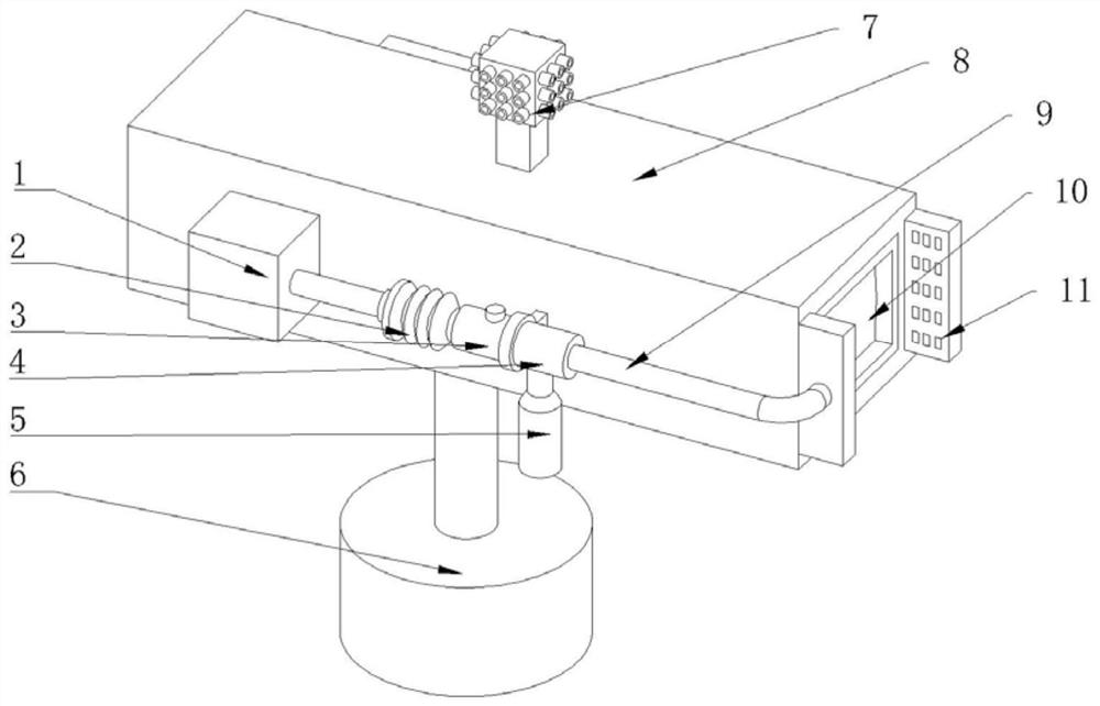
[0018] Example 1 is attached figure 1 As shown, a kind of intelligent monitoring equipment, comprises camera, bracket 6, controller, dust detector 7, vacuum cleaner and housing 8 installed on the camera, bracket 6 is positioned at the bottom of housing 8, and the mirror surface 10 of camera is positioned at housing On one side of 8, a functional module, a video receiving and output device and a power supply device are arranged at the position of the camera in the housing 8, and the camera, the functional module and the video receiving and output device are respectively connected with the power supply device, and the functional module is composed of a power supply module, a wireless radio frequency module , network transmission module, image storage module or bluetooth module and other electrical connections; the power supply device includes a battery, the battery is electrically connected to the photovoltaic solar panel, the controller, the dust detector 7 and the vacuum cleane...

Embodiment 2

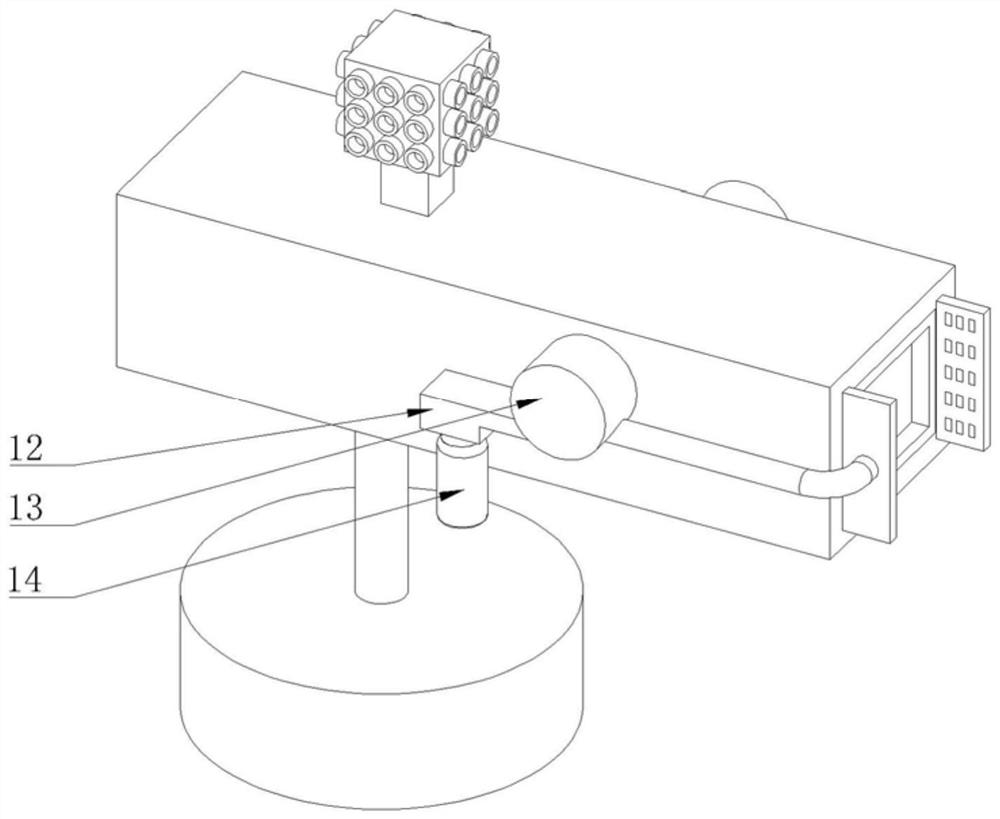
[0020] The difference between embodiment 2 and embodiment 1 is only the change of the vacuum cleaner structure, such as figure 2 As shown, the vacuum cleaner includes a suction pipe 9, an electric blower chamber 13, a dust collection chamber 12 and a dust collection bag 14 connected in sequence, the electric blower chamber 13 communicates with the dust collection chamber 12, and the dust collection bag 14 is located at the bottom of the dust collection chamber 12 , the dust collection bag 14 is made of gauze into a bag-like structure, and there are tiny air holes on the gauze, and the size of the air holes is smaller than the size of the dust, which does not affect dust collection and exhaust. The dust cover 11, the dust collection cover 11 faces the mirror 10, and the electric blower chamber 13 is provided with an electric blower, and the electric blower is electrically connected to the storage battery. During use, electric blower starts, and negative pressure is formed in t...


PUM


Abstract

This application discloses a kind of intelligent monitoring equipment in the field of monitoring equipment technology, including a camera, a power supply device and a housing installed on the camera head, and the housing is provided with a vacuum cleaner, a dust detector and a dust detector electrically connected to the power supply device. A controller, the output end of the dust detector is electrically connected to the input end of the controller, and the output end of the controller is electrically connected to the input end of the vacuum cleaner. There are at least two vacuum cleaners, which are respectively arranged on both sides of the mirror surface. The vacuum cleaner includes a dust suction port facing the mirror. The intelligent monitoring device of the present invention adopts pre-action, that is, vacuuming is performed before the dust adheres to the mirror surface, so even if it is windy and rainy, it will not interact with dust, so that the mirror surface can be kept clean all the time. The cleaning step is avoided, and the shooting quality of the intelligent monitoring equipment is also guaranteed.

Description

technical field [0001] The invention belongs to the technical field of monitoring equipment, and in particular relates to an intelligent monitoring equipment. Background technique [0002] Monitor refers to the general term for recording and storing video and audio signals by using camera storage equipment, such as the surveillance camera disclosed in Chinese patent CN102984445A, including a camera and a housing installed on the camera, in which functional modules, video receiving The output device and power supply device, camera, functional module and video receiving and output device are respectively connected to the power supply device. With the increasing popularity of closed-circuit monitoring in civil and commercial purposes, monitors are widely used in various fields, in enterprise management and social security. Both play the role of escort. [0003] However, for outdoor monitors, due to long-term exposure to the air, passing vehicles and pedestrians will cause dust...

Claims


Application Information

Patent Timeline
Patent Type & Authority Patents(China)
IPC IPC(8): H04N7/18H04N5/225B08B5/04
CPCH04N7/183B08B5/04H04N23/51
Inventor 袁勇
Owner 巫溪县致恒科技有限公司
Why Eureka
Try Eureka