Printed matter detection device based on area-array camera

A detection device, area scan camera technology, applied in measurement devices, testing moving boards, material analysis by optical means, etc., can solve problems such as lowering of shooting quality, inability to solve positioning problems, bending and other problems

Inactive Publication Date: 2021-07-06
何峰
View PDF0 Cites 0 Cited by
  • Summary
  • Abstract
  • Description
  • Claims
  • Application Information

AI Technical Summary

Problems solved by technology

[0002] Under high-speed printing, once a quality problem occurs, it will be continuous, resulting in a large amount of waste. Therefore, during high-speed printing, it is necessary to monitor the printing quality in real time. The usual monitoring methods include stroboscopic detection, line scan cameras and area scans. Cameras, generally speaking, stroboscopic detection has higher requirements for staff, while line-scan cameras are more expensive, and area-scan cameras are between the two, with acceptable costs and a high degree of automation
[0003] Due to the constraints of the camera shutter and exposure, under the condition of high-speed printing, there will be some smear in the shooting of the area scan camera, and there will be more invalid shooting due to inaccurate positioning during shooting. In order to solve this problem, By making the camera move synchronously with the printed matter, the accuracy and clarity of shooting can be improved, but the camera moves with the printed matter at high speed, and it will bear a large force every time it changes direction and turns back, which greatly reduces the service life of the camera. The weight of the camera may bend the conveyor chain when it moves with the conveyor chain, reducing the shooting quality
[0004] Secondly, the positioning problem cannot be solved, the shooting accuracy may be insufficient, and there is still a large repetition. At the same time, even if the servo motor is lacking feedback, it is difficult to maintain complete synchronization, which reduces the shooting quality.
[0005] Finally, the paper is soft and bends under its own weight as it moves along the conveyor rollers, distorting the photographs taken

Method used


Image

  • Printed matter detection device based on area-array camera
  • Printed matter detection device based on area-array camera
  • Printed matter detection device based on area-array camera

Examples


Embodiment Construction

[0022] The following will clearly and completely describe the technical solutions in the embodiments of the present invention with reference to the accompanying drawings in the embodiments of the present invention. Obviously, the described embodiments are only some, not all, embodiments of the present invention. Based on the embodiments of the present invention, all other embodiments obtained by persons of ordinary skill in the art without making creative efforts belong to the protection scope of the present invention.

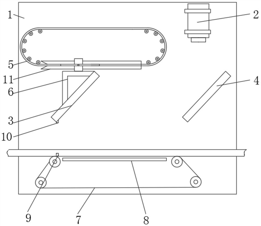
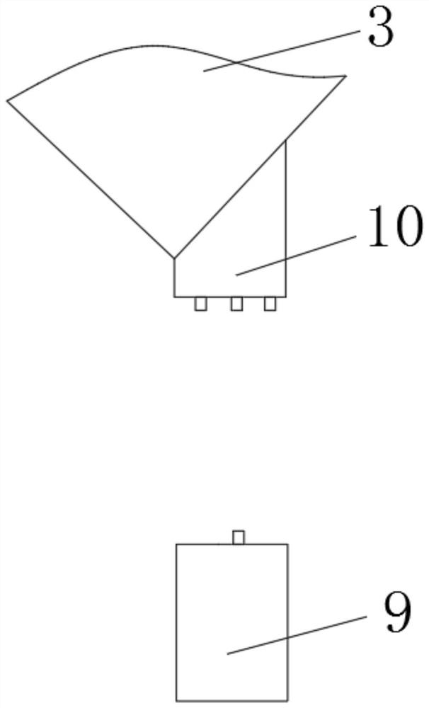
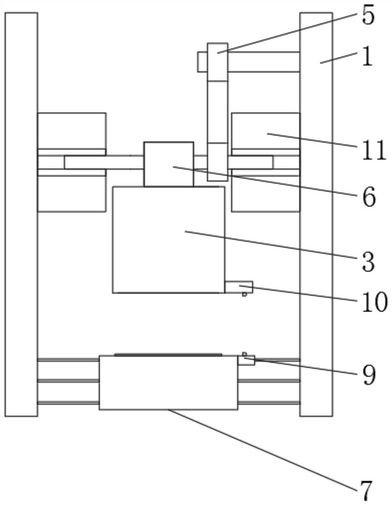
[0023] see figure 1 , a printed product detection device based on an area array camera, comprising a support frame 1, a camera 2 is fixedly installed on the support frame 1, the printed paper passes through the support frame 1 horizontally, and the support frame 1 is provided with a movable reflector against the moving direction of the paper Mirror 3 and fixed reflective mirror 4, movable reflective mirror 3 and fixed reflective mirror 4 all form an angle of f...


PUM


Abstract

The invention relates to the technical field of printing equipment, and discloses a printed matter detection device based on an area-array camera. The device comprises a support frame, a camera is fixedly mounted on the support frame, and a movable reflector and a fixed reflector are arranged on the support frame in the moving direction of paper. According to the printed matter detection device based on the area-array camera, the moving speed of the movable reflector is kept consistent with the speed of paper, then images shot by the camera are kept unchanged, and damage to the camera is small; secondly, an alignment piece A, an alignment piece B and an speed measuring piece are matched, the speed of a driving chain and a conveying belt and the speed of the conveying belt and printing are fed back, then adjustment is carried out, and operation at the same speed is ensured; and the paper is always attached to the conveying belt through electrostatic adsorption, the level of the paper during shooting is guaranteed, and the imaging quality is improved. Meanwhile, a friction force between the conveying belt and the paper ensures synchronous operation of the paper and the conveying belt, and the speed difference between the conveying belt and the printing speed can be eliminated.

Description

technical field [0001] The invention relates to the technical field of printing equipment, in particular to a printed product detection device based on an area array camera. Background technique [0002] Under high-speed printing, once a quality problem occurs, it will be continuous, resulting in a large amount of waste. Therefore, during high-speed printing, it is necessary to monitor the printing quality in real time. The usual monitoring methods include stroboscopic detection, line scan cameras and area scans. Cameras, generally speaking, stroboscopic detection has higher requirements for staff, while line-scan cameras are more expensive, and area-scan cameras are between the two, with acceptable costs and a high degree of automation. [0003] Due to the constraints of the camera shutter and exposure, under the condition of high-speed printing, there will be some smear in the shooting of the area scan camera, and there will be more invalid shooting due to inaccurate posit...

Claims


Application Information

Patent Timeline
Patent Type & Authority Applications(China)
IPC IPC(8): G01N21/86G01N21/01
CPCG01N21/01G01N21/86G01N2021/8663
Inventor 何峰
Owner 何峰
Why Eureka
Try Eureka