Acrobatic bracket

A technology of acrobatics and support rods, applied in the field of acrobatics brackets, can solve the problems of inconvenient carrying and heavy weight for performances

Inactive Publication Date: 2019-02-26
吴波
View PDF1 Cites 0 Cited by
  • Summary
  • Abstract
  • Description
  • Claims
  • Application Information

AI Technical Summary

Problems solved by technology

With the above structure, the motor drives the eccentric shaft to rotate, thereby driving the rotation and swing of the pendulum, which greatly increases the viewing performance of acrobatics and programs; at the same time, the supporting legs are of a foldable structure, which can be folded when not in use It can be folded up to reduce the occupied space and facilitate transpo...

Method used


Image

  • Acrobatic bracket

Examples


Embodiment Construction

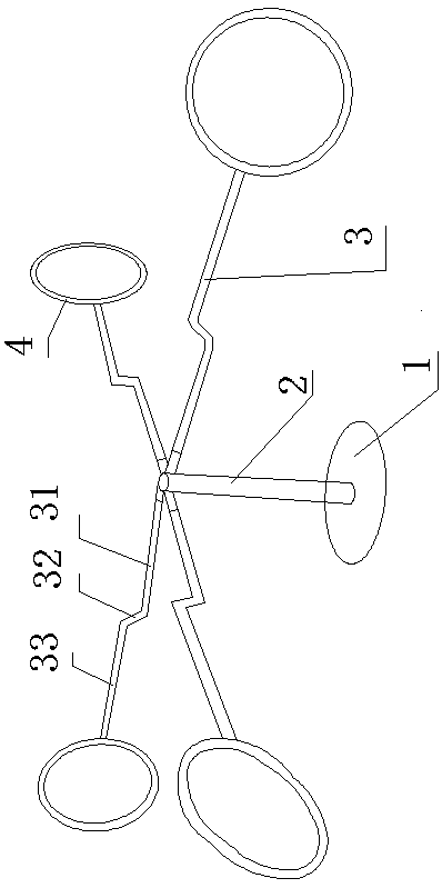
[0017] like figure 1 As shown, an acrobatic stand includes a base 1, a support rod 2, a rotating shaft, a cross bar 3, and a ring 4.

[0018] A supporting rod 2 is arranged on the base 1, a rotating shaft is arranged on the top of the supporting rod 2, the rotating shaft is arranged vertically, a plurality of crossbars 3 are arranged in the radial direction of the rotating shaft, and a ring 4 is arranged at the end of the crossbar 3.

[0019] The crossbar is detachable, and when the acrobatics are performed, the crossbar is inserted on the rotating shaft, and after the performance, the crossbar can be dismantled for easy storage.

[0020] The cross bar is a Z-shaped mechanism, including a first cross bar 31, a vertical bar 32, and a second cross bar 33. The first cross bar 31 is arranged on the rotating shaft, and the end of the first cross bar 31 is provided with a vertical bar 32, and the vertical bar 32 is arranged upward , the upper end of the vertical bar 32 is provided ...


PUM

PropertyMeasurementUnit
Angleaaaaaaaaaa

Abstract

The invention discloses an acrobatic bracket, and belongs to the technical field of acrobatic performance tools. The acrobatic bracket comprises a base, a supporting rod, a rotating shaft, a pluralityof transverse rods and circular rings; the supporting rod is arranged on the base, the rotating shaft is arranged at the top of the supporting rod, the rotating shaft is vertically arranged, the rotating shaft is radially provided with the transverse rods, and the circular rings are arranged at the tail ends of the transverse rods. The transverse rods are Z-shaped mechanisms, comprise first transverse rods, vertical rods and second transverse rods, the first transverse rods are arranged on the rotating shaft, the vertical rods are arranged at the tail ends of the first transverse rods, the vertical rods are arranged upward, the upper ends of the vertical rods are provided with the second transverse rods, and the second transverse rods are provided with the circular rings. The acrobatic bracket is provided for the deficiencies in the prior art, and has the advantages that the structure is simple, the design is ingenious, the transverse rods are detachably arranged on the supporting rod, the weight is light, carrying out is convenient, and the acrobatic bracket is very suitable for long-distance performance.

Description

technical field [0001] The invention relates to an acrobatic bracket, which belongs to the technical field of acrobatic tools. Background technique [0002] The Chinese invention patent with the notification number CN 204134234 U and the announcement date of February 4, 2015 discloses a foldable electric rotating swing frame, including a square base, a rotating column, a fixed ring, fixed feet, a motor, a reducer, and an eccentric shaft , a swing frame and a supporting foot, the top of the square base is provided with a rotating column, and a fixing ring is set on the rotating column, and the fixing ring is connected with the supporting foot, and the supporting foot includes a folding leg, a supporting leg and a self-locking rotating buckle, The support legs are set on the ground, one end of the support legs is connected to the square base, and the other end is connected to the folding legs; one end of the folding legs is connected to the fixing ring, and the middle part of ...

Claims


Application Information

Patent Timeline
IPC IPC(8): A63J5/02A63J7/00
CPCA63J5/02A63J7/00
Inventor 吴波
Owner 吴波
Why Eureka
Try Eureka