Positioning fixture

A technology for positioning fixtures and fixtures, which is applied in the field of machinery, can solve the problems of cumbersome use, increased labor costs, and low production efficiency, and achieve the effects of simple and reasonable overall structure design, simple and exquisite structure, and reduced production costs

Inactive Publication Date: 2019-02-26
TAIZHOU HUAFENG TECH EQUIP
View PDF0 Cites 0 Cited by
  • Summary
  • Abstract
  • Description
  • Claims
  • Application Information

AI Technical Summary

Problems solved by technology

[0002] In the traditional welding process, the welding of the workpiece to be welded is usually through simple cooperation between workers. Since the fixed clamping cannot be carried out stably, the stability and accuracy of welding cannot be guaranteed, and it directly leads to The production efficiency is low and the qualification rate of workpiece products is not high, which increases the difficulty of welding and labor costs, and cannot meet the needs of modern workpiece welding batch production, and the current positioning welding structure is relatively complicated, which makes it cumbersome to use and low production efficiency , which increases the production cost

Method used


Image

  • Positioning fixture

Examples


Embodiment Construction

[0016] The present invention will be further explained below in conjunction with the accompanying drawings and embodiments.

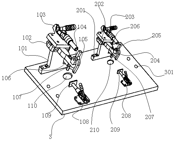
[0017] Such as figure 1 Shown, a kind of positioning jig comprises positioning base 3, and the first positioning unit and the second positioning unit that are located on positioning base 3; The first positioning unit comprises the first clamping unit and the first support unit; The first clamping The unit includes a first inverted T-shaped support 101, a first movable platform 102 and a first clamping fixture 103 adapted to the first movable platform 102; one end of the first movable platform 102 is adapted to the first clamping fixture 103 The other end of the first movable table 102 is provided with a first support base 104 and a first movable jaw 105 located on the first support base 104; a first fixed frame 106 is provided on the first inverted T-shaped support 101, and A fixed bracket 106 is provided with a first arc-shaped fixed claw 107; the fir...


PUM

PropertyMeasurementUnit
Thicknessaaaaaaaaaa

Abstract

The invention discloses a positioning fixture. The positioning fixture comprises a positioning base, a first positioning unit and a second positioning unit, wherein the first positioning unit and thesecond positioning unit are arranged on the positioning base; the first positioning unit comprises a first clamping unit and a first supporting unit; the first clamping unit comprises a first inversely T-shaped support, a first movable table and a first clamp matched with the first movable table; one end of the first movable table is matched with the first clamp, a second inversely T-shaped support is provided with a second fixing frame, and the height ratio of the first inversely T-shaped support to the second inversely T-shaped support is (2-3):(1-1.5). According to the positioning fixture,the integral structural design is simple and reasonable, all components are matched with one another, the requirements of products can be met, and the function of supporting or clamping or positioningworkpiece components to be positioned and welded can be achieved so that the workpiece components to be welded can be attached point to point or face to face. After welding is finished by a welding fixture, the workpiece components are assembled into a complete workpiece through welding.

Description

technical field [0001] The invention relates to the mechanical field, in particular to a fixture structure used in tack welding. Background technique [0002] In the traditional welding process, the welding of the workpiece to be welded is usually through simple cooperation between workers. Since the fixed clamping cannot be carried out stably, the stability and accuracy of welding cannot be guaranteed, and it directly leads to The production efficiency is low and the qualification rate of workpiece products is not high, which increases the difficulty of welding and labor costs, and cannot meet the needs of modern workpiece welding batch production, and the current positioning welding structure is relatively complicated, which makes it cumbersome to use and low production efficiency , increasing production costs. Contents of the invention [0003] The purpose of the present invention is to overcome the problems of the prior art and provide a positioning fixture. [0004]...

Claims


Application Information

Patent Timeline
IPC IPC(8): B23K37/04
CPCB23K37/0443
Inventor 黄光明
Owner TAIZHOU HUAFENG TECH EQUIP
Why Eureka
Try Eureka