Damper device of a hydraulic unit of a vehicle brake device with a damper chamber

A buffer device and vehicle braking technology, applied in the direction of brakes, brake components, vehicle components, etc., to achieve the effect of avoiding power loss

Active Publication Date: 2019-02-26
ROBERT BOSCH GMBH
View PDF13 Cites 1 Cited by
  • Summary
  • Abstract
  • Description
  • Claims
  • Application Information

AI Technical Summary

Problems solved by technology

[0004] However, power losses also occur through damping of the brake fluid flow, which should be compensated by the associated piston pumps

Method used


Image

  • Damper device of a hydraulic unit of a vehicle brake device with a damper chamber
  • Damper device of a hydraulic unit of a vehicle brake device with a damper chamber
  • Damper device of a hydraulic unit of a vehicle brake device with a damper chamber

Examples


Embodiment Construction

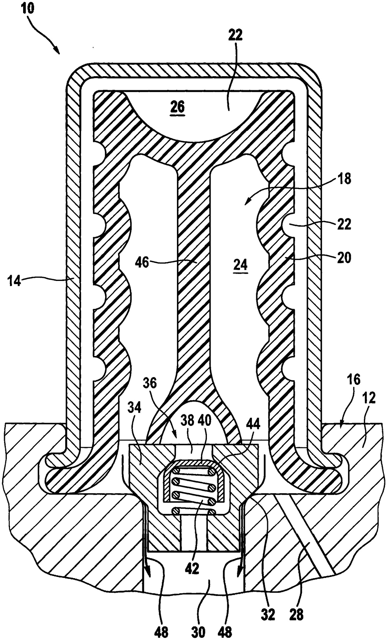
[0023] exist figure 1 The buffer device 10 of the hydraulic assembly of the vehicle brake system is shown in . The damping device 10 is located here on a housing 12 of the hydraulic unit, which is designed here as a square block made of aluminum. A cap-shaped damper housing 14 protrudes from the housing 12 . In this case, the connection between the housing 12 and the edge section of the cap-shaped damper housing 14 is designed as a stationary and fluid-tight packing 16 .

[0024] The buffer device housing 14 is enclosed in its interior with a cylindrical buffer interior space 18, which is also referred to figure 1 The lower end is defined by the housing 12 . A likewise cap-shaped damping membrane 20 is located in the damping interior 18 . The damping membrane is formed from an elastic material and is designed with a plurality of elevations 22 on its outer side. The damping film 20 is enclosed in the packing 16 at its lower section and is held there in a stationary manner ...


PUM


Abstract

A damper device (10) of a hydraulic unit of a vehicle brake device is designed with a damper chamber (26) whose chamber volume is variable, and a throttle (36) arranged downstream of the damper chamber (26). According to the invention, the throttle (36) has a variable throttling effect and this throttle effect is variable as a function of the chamber volume.

Description

technical field [0001] The invention relates to a buffer device of a hydraulic assembly of a vehicle braking device, which has a buffer chamber whose volume can be changed and a throttle valve connected in series with the buffer chamber. Background technique [0002] For hydraulic vehicle brake systems, which are used in particular for passenger cars and trucks, for example, pressure pulse dampers are used in order to avoid pressure pulses and the resulting noise within the vehicle brake system. Pressure pulses occur when the brake fluid is compressed by means of the piston pump. In addition, pressure waves are generated when the valves are switched. [0003] Such a damping device for hydraulic brake systems is known, for example, from DE 103 05 310 B4. The pressure pulse damper described here has a damping chamber whose chamber volume can be varied in that an elastomer core arranged in the damping chamber is compressed when the pressure rises. The buffer chamber is conne...

Claims


Application Information

Patent Timeline
Patent Type & Authority Applications(China)
IPC IPC(8): B60T17/00B60T8/40
CPCB60T8/4068B60T17/00B60T8/40B60T8/42
Inventor D·布伦德费尔
Owner ROBERT BOSCH GMBH
Why Eureka
Try Eureka