fuel high pressure pump

A high-pressure pump and fuel technology, applied in fuel injection devices, charging systems, engine components, etc., can solve problems such as restrictions, large bearing flow, etc., and achieve the effect of saving time and materials

Active Publication Date: 2017-06-13
ROBERT BOSCH GMBH
View PDF6 Cites 0 Cited by
  • Summary
  • Abstract
  • Description
  • Claims
  • Application Information

AI Technical Summary

Problems solved by technology

The prior art also discloses bearing volume limiting throttles, in which the bearing volume limiting throttles are respectively installed in the bearing points in order to thereby limit the maximum bearing flow rate

Method used


Image

  • fuel high pressure pump
  • fuel high pressure pump
  • fuel high pressure pump

Examples


Embodiment Construction

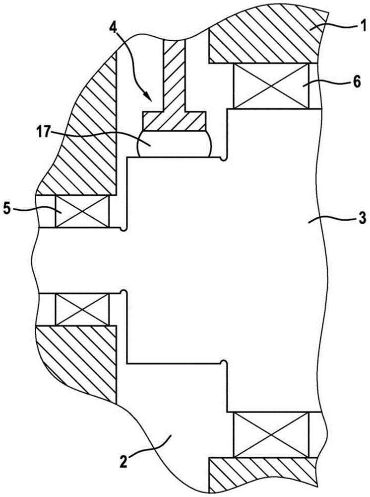
[0021] figure 1 A schematic sectional view of the pump housing 1 shown in detail of a high-pressure fuel pump is shown. A high-pressure fuel pump supplies fuel from a low-pressure system into a high-pressure accumulator, from which fuel is withdrawn by a fuel injector for injection into a combustion chamber of an internal combustion engine. The internal combustion engine is preferably a diesel powered self-ignition internal combustion engine.

[0022] The high-pressure fuel pump has a pump housing 1 in which a drive chamber 2 is formed. Fuel is delivered from the low-pressure system to the drive compartment 2 . A drive shaft 3 is supported in the pump housing 1 , protrudes into the drive chamber 2 and interacts with the pump piston 4 via a roller tappet 17 . The pump piston 4 conveys the fuel entering the pump working chamber into a high-pressure accumulator, the so-called common rail. The fuel entering the pump working chamber is dosed by a metering device (not shown here...


PUM


Abstract

The invention relates to a fuel injection system, in particular for a common rail injection system of an internal combustion engine, comprising a pump housing (1) in which a driveshaft (3) and at least one pump piston (4) that interacts with the driveshaft (3) are arranged in a fuel-filled engine compartment (2). The engine compartment (2) is connected to a low-pressure system of the injection system, and the driveshaft (3) is mounted by means of a first bearing (5) and a second bearing (6). A recess (7) is provided in the pump housing (1) between the engine compartment (2) and the low-pressure system, and an insert part (8) is arranged in the recess (7). Furthermore, the insert part (8) has at least one radially and / or axially arranged bore (9) for a quantity of lubricant in order to ensure a lubricant and coolant quantity for the engine compartment (2) of the high-pressure fuel pump.

Description

technical field [0001] The invention relates to a high-pressure fuel pump for a fuel injection system, in particular for a common rail injection system of an internal combustion engine, having a pump housing in which a fuel-filled drive chamber is arranged. A drive shaft interacting with at least one pump piston, wherein the drive chamber is connected to the low-pressure system of the injection system, and the drive shaft is supported via a first bearing and a second bearing, wherein the drive shaft is mounted in the pump housing A groove is arranged between the device chamber and the low pressure system. Background technique [0002] Such a high-pressure fuel pump is known from DE 10 2009 027 146 A1. The high-pressure fuel pump has a suction-side low-pressure area, in which an overflow valve is arranged, the overflow valve having a valve housing fastened in the pump housing, the valve housing having Inlet, outlet, valve body and valve spring. The device is therefore char...

Claims


Application Information

Patent Timeline
Patent Type & Authority Patents(China)
IPC IPC(8): F02M63/00
CPCF02M63/0001
Inventor M·拉姆
Owner ROBERT BOSCH GMBH
Why Eureka
Try Eureka