
Distance detecting device and distance detecting method thereof

A technology of distance detection and relative distance, applied in measuring devices, instruments, using ultrasonic/sonic/infrasonic waves, etc., can solve the problem that the relative distance between the receiver and the signal source cannot be accurately calculated

Active Publication Date: 2019-02-26
ACER INC
View PDF12 Cites 0 Cited by
  • Summary
  • Abstract
  • Description
  • Claims
  • Application Information

AI Technical Summary

Problems solved by technology

Although the relative distance can be calculated when the distance between the receiver and the signal source is fixed, when the relative speed between the receiver and the signal source is not equal to 0, it will not be possible to accurately calculate the distance between the receiver and the signal source. relative distance

Method used


Image

  • Distance detecting device and distance detecting method thereof
  • Distance detecting device and distance detecting method thereof
  • Distance detecting device and distance detecting method thereof

Examples


Embodiment Construction

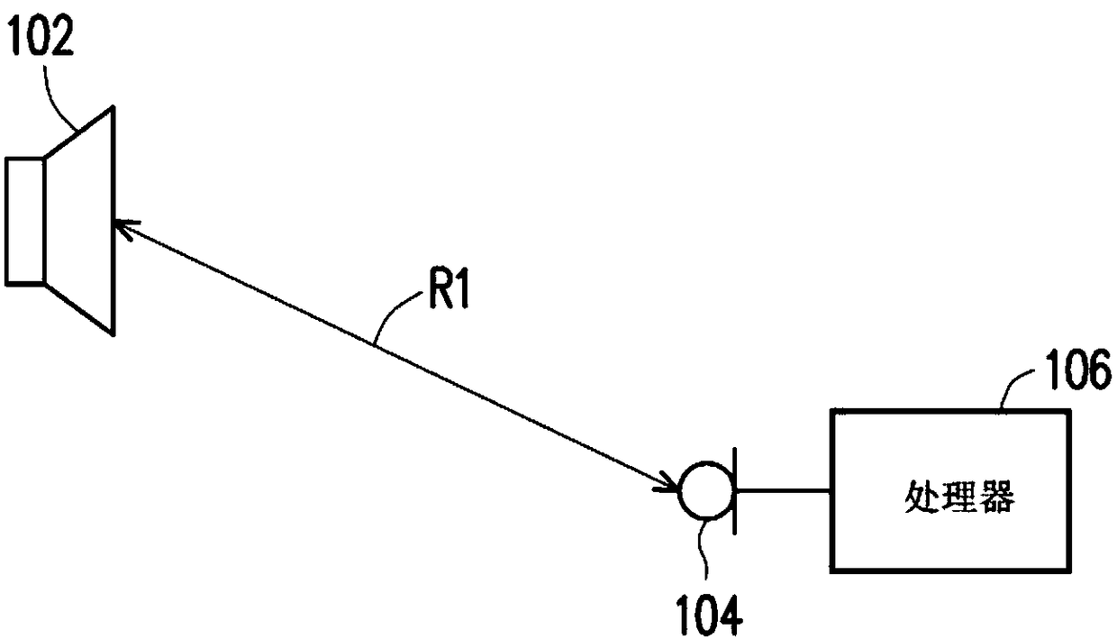
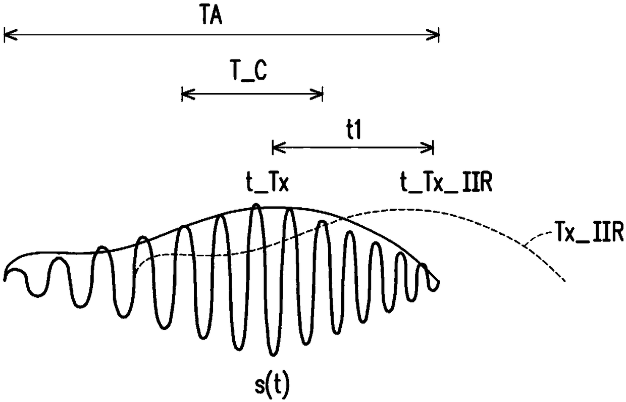
[0043] figure 1 Is a schematic diagram of a distance detection device according to an embodiment of the present invention, please refer to figure 1 . The distance detection device includes a speaker 102, a sound receiver 104, and a processor 106, wherein the processor 106 is coupled to the sound receiver 104. The speaker 102 is used to output a preset sound signal, and the preset sound signal has a time-varying amplitude and frequency. That is, the preset sound signal can correspond to different amplitudes and frequencies at different time points. Furthermore, the speaker 102 may output a preset sound signal every other time period, for example, in this embodiment, the preset sound signal s(t) may be expressed by the following formula:

[0044] s(t)=A(t)·cos[2π·f(t)·t] (1)

[0045] Where t is the time, A(t) is the amplitude of the preset sound signal s(t), and f(t) is the frequency of the preset sound signal s(t). The time length of each time period can be set to, for example, th...


PUM


Abstract

The invention provides a distance detecting device and a distance detecting method thereof. The method comprises the steps: correcting the frequency value of a preset sound signal through a Doppler effect according to the relative speed, calculated previously, between a loudspeaker and a sound receiver; performing cross correlation calculation of the corrected preset sound signal and the sound signal received by the sound receiver so as to generate a cross correlation signal; and calculating the distance between the loudspeaker and the sound receiver according to the time corresponding to a packaging amplitude value of the cross correlation signal and the time when the loudspeaker outputs a packaging amplitude value of the preset sound signal.

Description

Technical field [0001] The invention relates to a detection device, in particular to a distance detection device and a distance detection method thereof. Background technique [0002] Generally speaking, when calculating the relative distance between the signal source and the receiver, the time difference between the signal output by the signal source and the signal received by the receiver can be calculated by calculating the cross correlation between the received signal and the original output signal at each time point (Cross -Correlation), where the time corresponding to the maximum value of the cross-correlation signal is the time of receiving the signal, and the time of the output signal is known, so the relative distance can be calculated based on the time difference between the time of receiving the signal and the time of the output signal . In this way, the relative distance can be calculated when the distance between the receiver and the signal source is fixed, but when...

Claims


Application Information

Patent Timeline
IPC IPC(8): G01B17/00
CPCG01B17/00
Inventor 杜博仁张嘉仁曾凯盟
Owner ACER INC
Learn More