Speed detecting device and method

A technology of speed detection and detection coils, applied in speed/acceleration/shock measurement, measuring devices, linear/angular velocity measurement, etc., can solve the problems of changes in estimation results and the inability to detect the moving speed of moving objects with high precision, and achieve high precision The effect of movement speed

Active Publication Date: 2019-02-26
NABLESCO CORP
View PDF11 Cites 1 Cited by
  • Summary
  • Abstract
  • Description
  • Claims
  • Application Information

AI Technical Summary

Problems solved by technology

[0005] However, unless various conditions such as the shape of the yoke, the arrangement of the excitation coil and the detection coil, and the distance from the moving body are optimized, the moving speed of the moving body cannot be detected with high precision.
For example, if the gap between the excitation coil or detection coil and the moving body changes, the estimated result of the moving speed of the moving body may change.

Method used


Image

  • Speed detecting device and method
  • Speed detecting device and method
  • Speed detecting device and method

Examples


Embodiment Construction

[0050] Hereinafter, one embodiment of the present disclosure will be described with reference to the drawings. In addition, in the drawings attached to the specification of this application, the scales, the aspect ratios, and the like are appropriately changed and exaggerated from the actual scales and aspect ratios for the sake of illustration and understanding.

[0051] Also, terms such as "parallel", "orthogonal", and "same", values ​​of lengths or angles, etc. used in this specification to designate shapes or geometric conditions and their degrees are not limited to strict meanings, The range in which the same degree of functionality can be expected is also included for interpretation.

[0052]

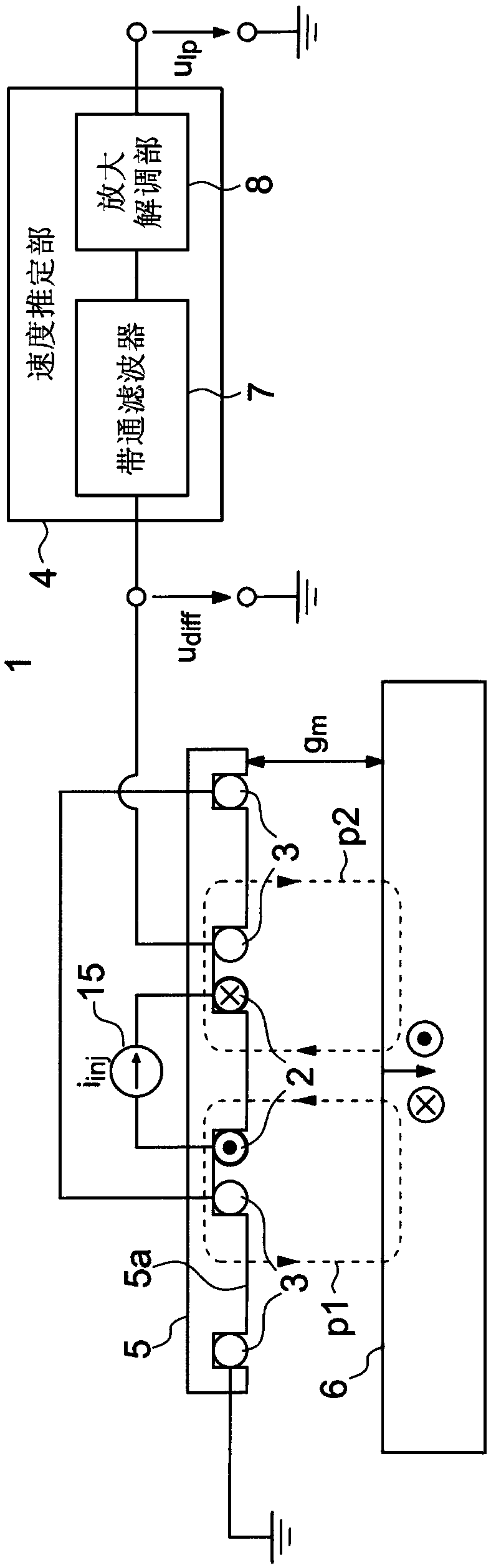
[0053] figure 1 It is a figure explaining the basic principle of the speed detection apparatus 1 of this embodiment. figure 1 The speed detection device 1 includes an exciting coil 2 , a speed estimation unit 4 and two detection coils 3 . The number of turns of the two detect...


PUM


Abstract

The invention relates to a speed detecting device and a speed detecting method which detect the speed in a non-contact manner, and which can detect the moving speed of a relative moving body with highprecision even if a gap between an excitation coil or a detection coil and the relative moving body changes. The device includes more than one excitation coil for generating a magnetic flux corresponding to an alternating current; a plurality of detection coils each generating an induced voltage corresponding to a magnetic flux produced by an eddy current generated on a conductive relative movingbody, the eddy current being generated so as to correspond to a moving speed of the relative moving body; a current and voltage measuring portion for measuring current flowing through the excitationcoil and the voltage at two ends of the excitation coil; a gap estimation portion for estimating, based on a current flowing through the excitation coil and a voltage across the excitation coil, a gapbetween the relative moving body and the excitation coil; and a speed estimation portion for estimating, based on the gap estimated by the gap estimation portion and the induced voltage generated ineach of the plurality of detection coils, the moving speed of the relative moving body.

Description

technical field [0001] The invention relates to a speed detection device and a speed detection method for detecting speed in a non-contact manner. Background technique [0002] Non-contact speed sensors are used in a wide range of industrial fields such as machining, assembly, and moving bodies. Generally, these speed sensors use optical (camera, encoder) or electromagnetic (magnetoresistive, Hall elements) technology. That is, the conventional speed sensor calculates the speed based on the temporal change of the optical or magnetic discontinuity characteristics of the moving object to be measured. Therefore, velocity measurement cannot be performed on a perfectly flat moving body that does not have discontinuities. [0003] Velocity sensors using induced electromotive force generated by eddy currents are known as methods for detecting the moving speed of a perfectly flat moving object (see JP-A-8-233843 and JP-A-8-146024). In this type of speed sensor, two detection coil...

Claims


Application Information

Patent Timeline
Patent Type & Authority Applications(China)
IPC IPC(8): G01P3/66
CPCG01P3/66G01P3/49G01P3/505G01B7/14
Inventor M·弗兰克尔A·特伊苏约翰·W·克拉尔塚田裕介中村和人
Owner NABLESCO CORP
Why Eureka
Try Eureka