
Two-channel current sensor structure based on magnetic field detection

A current sensor, dual-channel technology, applied in the direction of measuring current/voltage, measuring electrical variables, voltage/current isolation, etc., can solve the problems of low detection accuracy, interference, etc., to improve detection accuracy, eliminate magnetic field interference, and improve signal-to-noise the effect of

Pending Publication Date: 2019-02-26
杭州思泰微电子有限公司
View PDF0 Cites 0 Cited by
  • Summary
  • Abstract
  • Description
  • Claims
  • Application Information

AI Technical Summary

Problems solved by technology

[0005] In order to solve the problem of low detection accuracy caused by interference from the magnetic field of adjacent channels, the present invention provides a dual-channel current sensor structure based on magnetic field detection, which can effectively suppress the magnetic interference of adjacent channels and improve detection accuracy

Method used


Image

  • Two-channel current sensor structure based on magnetic field detection
  • Two-channel current sensor structure based on magnetic field detection
  • Two-channel current sensor structure based on magnetic field detection

Examples


Embodiment 1

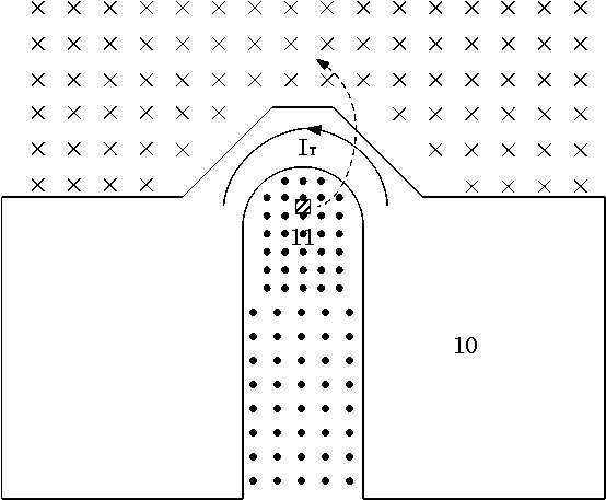
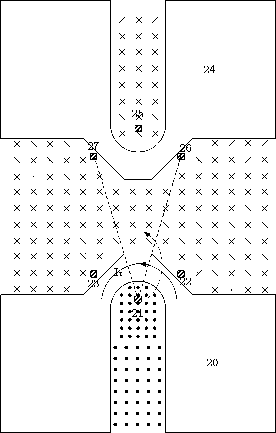
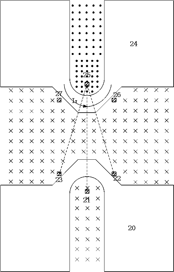
[0019] Embodiment one: see figure 2 , image 3 As shown, a dual-channel current sensor structure based on magnetic field detection includes two symmetrically arranged conductors 20 and 24, the conductors 20 and 24 themselves are symmetrical structures, and the U-shaped groove opening inside a conductor 20 is vertically mapped to A first inner Hall device 21 is arranged at the upper position, and two first outer Hall devices 22 and 23 are arranged at the position where the outer side is vertically mapped to the upper position, and the first outer Hall devices 22 and 23 are arranged on the line of symmetry of the conductor 20 itself. Symmetrically arranged, a second inner Hall device 25 is arranged in the opening of the U-shaped groove inside the other conductor 24, which is vertically mapped to the upper layer, and two second outer Hall devices 26 are arranged at the position where the outer side is vertically mapped to the upper layer and 27, the straight-line distances from...


PUM


Abstract

The invention relates to the technical field of current sensors, in particular to a two-channel current sensor structure based on magnetic field detection, which can effectively suppress magnetic interference of adjacent channels and improve detection precision. The two-channel current sensor structure comprises conductors with a U-shaped groove, and is characterized in that the number of the conductors is two and the conductors are symmetrically arranged, a first inner Hall device is disposed in a U-shaped groove opening in the inner side of one conductor and at a position vertically mapped to an upper layer, first outer Hall devices are disposed on the outer side of the one conductor and at positions vertically mapped to the upper layer, a second inner Hall device is disposed in a U-shaped groove opening in the inner side of the other conductor and at a position vertically mapped to the upper layer, second outer Hall devices are disposed on the outer side and at positions verticallymapped to the upper layer, the linear distances of the first inner Hall device to the second inner Hall device and to the second outer Hall devices are equal, and the linear distances of the second inner Hall device to the first inner Hall device and to the first outer Hall devices are equal.

Description

technical field [0001] The invention relates to the technical field of current sensors, in particular to a dual-channel current sensor structure based on magnetic field detection. Background technique [0002] The Hall effect defines the relationship between the magnetic field and the induced voltage in a Hall sensor: when a current passes through a conductor in a magnetic field, the magnetic field will generate a force perpendicular to the direction of electron motion on the electrons in the conductor, thereby A potential difference is generated in two directions perpendicular to the conductor and the magnetic field lines. The Hall device detects the change of the magnetic field and converts it into an electrical signal output, which can be used to monitor and measure various parameters, such as position, displacement, angle, angular velocity, rotational speed, etc., and can perform secondary transformation on these variables to measure pressure, Quality, liquid level, vel...

Claims


Application Information

Patent Timeline
Patent Type & Authority Applications(China)
IPC IPC(8): G01R15/20G01R19/00
CPCG01R15/202G01R19/00
Inventor 黄海滨殷晓宇杨超
Owner 杭州思泰微电子有限公司
Learn More