Rigid catenary busbar drilling mold

A drilling mold and rigid contact technology, which is applied in the direction of drilling molds for workpieces, etc., can solve the problems of increasing manpower consumption, increasing deformation of the contact between drilling and template holes, time-consuming and labor-intensive problems, etc.

Pending Publication Date: 2019-03-01
中铁一局集团电务工程有限公司 +1
View PDF0 Cites 0 Cited by
  • Summary
  • Abstract
  • Description
  • Claims
  • Application Information

AI Technical Summary

Problems solved by technology

[0005] Although the existing mold drilling positioning scheme is more convenient and efficient than using a ruler, this method is time-consuming and labor-intensive, and the mold is not easy to store and easily deformed, and the drill hole will contact the hole of the template after a long time of use Larger deformation will affect the drilling accuracy and construction efficiency
[0006] Not only that, when the existing mold drilling positioning scheme is implemented, one person needs to hold the mold, and the other person uses an electric drill to drill holes, which increases manpower consumption and construction costs

Method used


Image

  • Rigid catenary busbar drilling mold
  • Rigid catenary busbar drilling mold
  • Rigid catenary busbar drilling mold

Examples


Embodiment Construction

[0035] As stated in the background technology of this application, in the existing drilling positioning scheme, whether it is ruler measurement or the existing formwork measurement, it is time-consuming and laborious, the construction efficiency is low, and multiple people are required to assist in the operation, which increases the construction cost , increasing the construction time.

[0036] The embodiment of the present application provides a rigid catenary busbar drilling mold, which solves the problems of poor drilling accuracy, low construction efficiency, and high construction cost in the prior art.

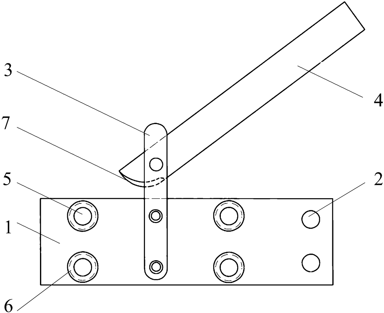
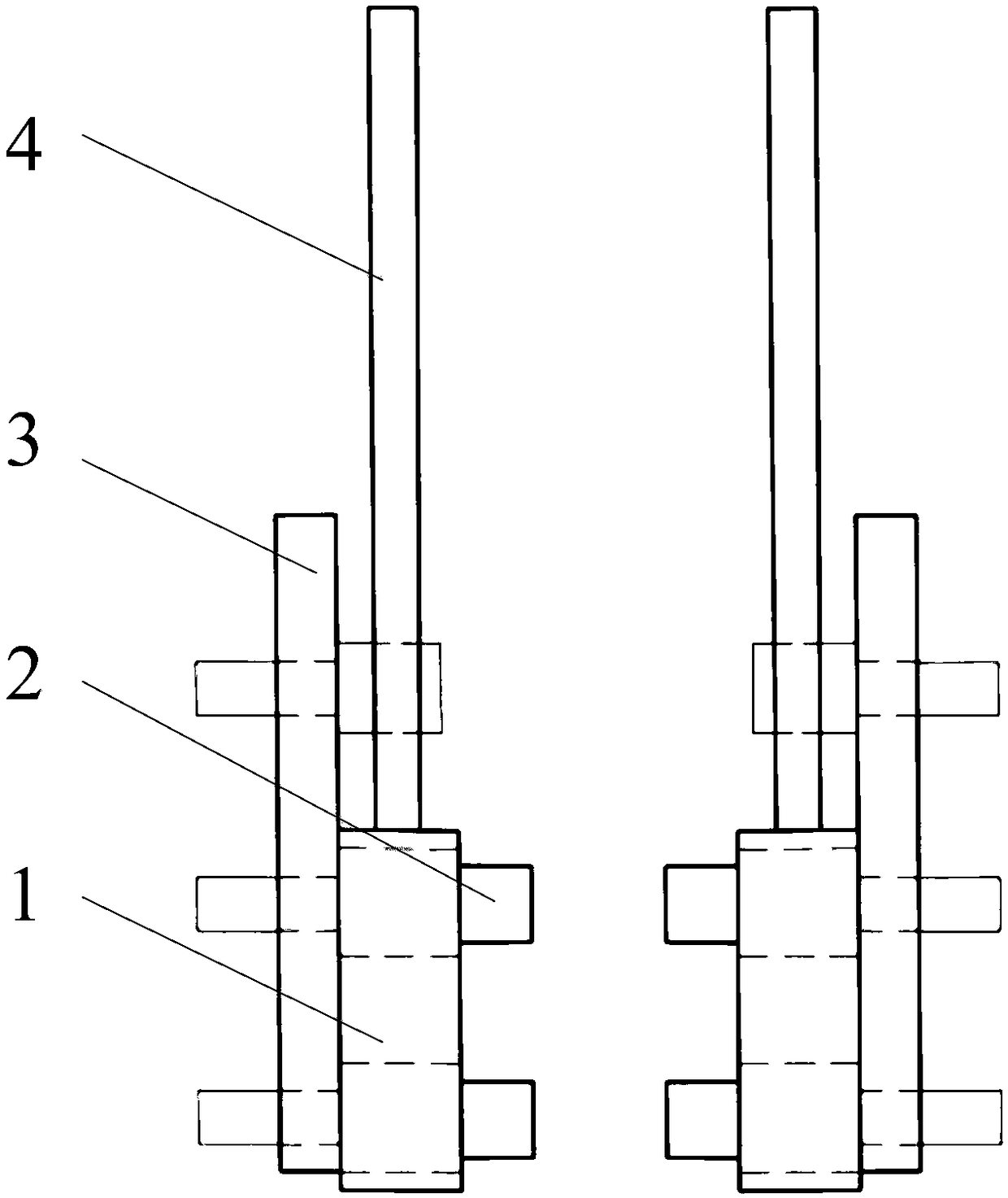
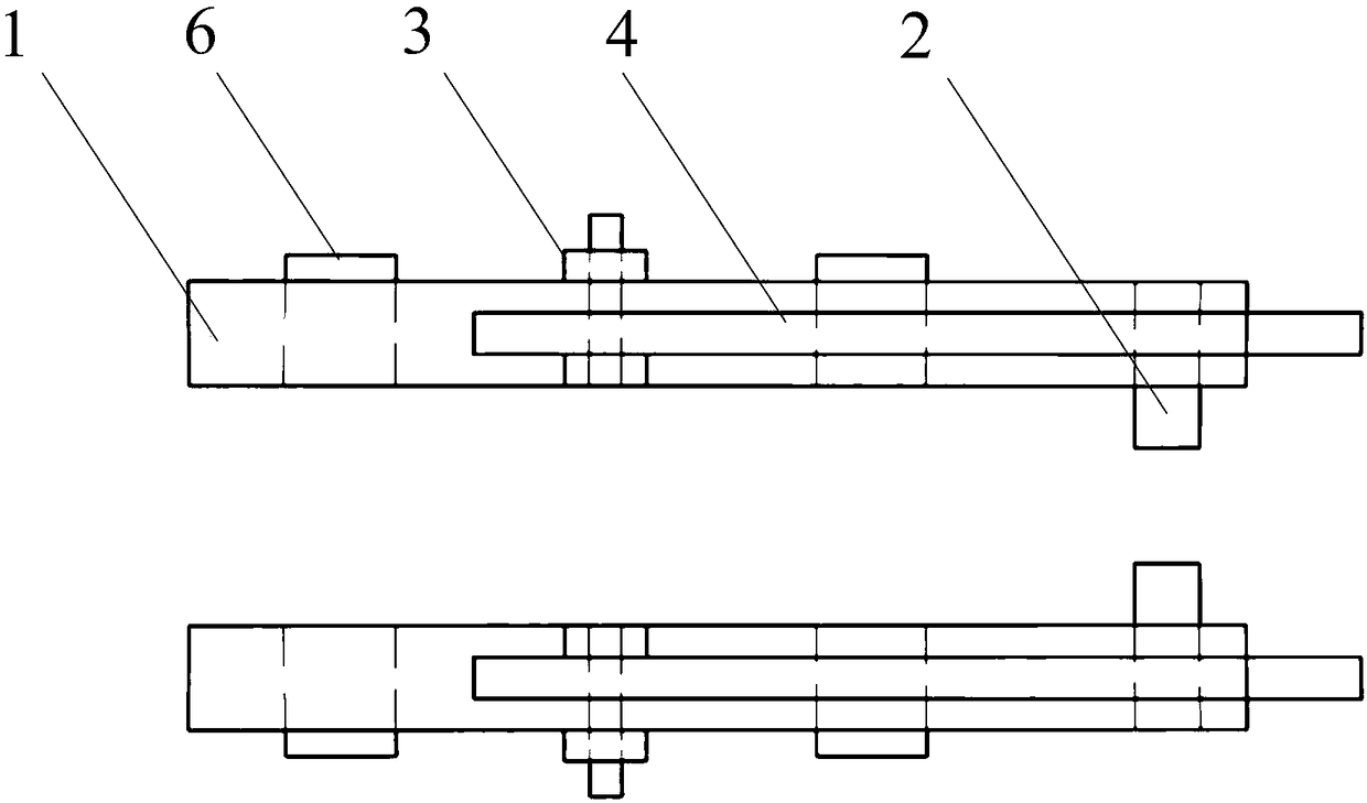
[0037] Such as figure 1 As shown, it is a schematic diagram of the overall structure of a rigid catenary busbar drilling die proposed in the embodiment of the present application. At the same time, in order to show the corresponding structural design more clearly, figure 2 and image 3 A side view and a top view of a rigid catenary busbar drilling mold proposed in the...


PUM


Abstract

The embodiment of the invention discloses a rigid catenary busbar drilling mold which comprises two drilling mold parts, wherein the structures of the two drilling mold parts are mirror images of eachother; a plurality of drilling holes are as same as actual busbar and are arranged on a mold plate of each drilling mold part to serve as drilling positioning holes; and a positioning part is arranged inside each mold plate, so that the mold plate and the busbar are closely attached. The mold plates and the busbar are firmly fixed through a connecting strip and a connecting plate, so that the precise positioning of the drilling position of the busbar is achieved through the drilling holes on the mold plates. The drilling holes on the drilling mold parts are completely processed according to the hole position of the busbar. The rigid catenary busbar drilling mold has the advantages that the drilling positioning of the drilling mold parts on the busbar is accurate, the fixing operation is simple and can be completed by one person independently, the drilling precision is improved, the construction efficiency is improved and the construction cost is reduced.

Description

technical field [0001] The application relates to the field of track construction, in particular to a drilling mold for rigid catenary busbars. Background technique [0002] At present, many underground lines of domestic urban rail transit use rigid catenary to supply power to electric buses. When using rigid catenary busbars for installation and construction, part of the busbars must be cut, drilled and then connected and installed. On average, two holes will be drilled every 230 meters (16 holes in each place). In the past, the measurement and positioning of boreholes mostly used rulers and markers to draw points. This method is time-consuming and laborious, and the error is large. greater than 1mm), resulting in the waste of busbars, which is very unfavorable for on-site construction. [0003] In the prior art, molds are usually used to solve the above problems. It is to use molds made of materials such as wood boards, plastic boards, and thin iron sheets, and punch h...

Claims


Application Information

Patent Timeline
Patent Type & Authority Applications(China)
IPC IPC(8): B23B47/28
CPCB23B47/28
Inventor 苏卓高建峰王征兵刘志川吴志勇高晓斌陈凯高思文刘晓东贺同堂高育栋鄂进宇
Owner 中铁一局集团电务工程有限公司
Why Eureka
Try Eureka