Transmission shaft deflection device and using method thereof

A deflection control, transmission shaft technology, applied in the direction of control devices, non-deflection wheel steering, brakes, etc.

Inactive Publication Date: 2019-03-01
ZHEJIANG ZHIRUI TECH GRP CO LTD
View PDF0 Cites 2 Cited by
  • Summary
  • Abstract
  • Description
  • Claims
  • Application Information

AI Technical Summary

Problems solved by technology

[0002] With the development of science and technology and the progress of society, the country has been promoting the development of high technology. In the field of power control, there has always been a relatively difficult technical problem, that is, how to artificially control the deflection of the transmission shaft by means of mechanical transmission, so as to control the transportation How to use the deflection of the transmission shaft to control the forward, rotation and braking of the scooter, the movement state of machines such as cars, most of the products on the market now rely on gravity induction, which has a certain delay, so there is an urgent need for a device to solve such problems

Method used


Image

  • Transmission shaft deflection device and using method thereof
  • Transmission shaft deflection device and using method thereof
  • Transmission shaft deflection device and using method thereof

Examples


Embodiment Construction

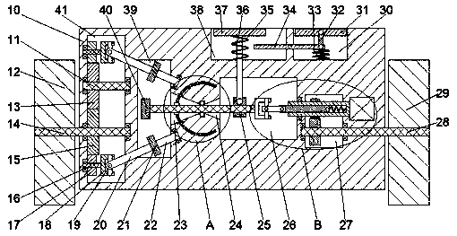
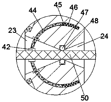
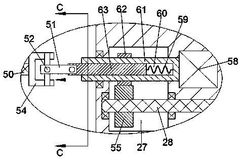
[0015] like Figure 1-Figure 4As shown, the transmission shaft deflection control device and its use method of the present invention include a main body 10, a tire driving chamber 41 is fixed inside the main body 10, and the main body 10 located on the right side of the tire driving chamber 41 A reversing cavity 39 is fixed inside, a pedal control cavity 26 is fixed in the main body 10 on the right side of the reversing cavity 39, and a pedal control cavity 26 is fixed in the main body 10 on the right side of the pedal control cavity 26. The power chamber 27, the first tapered groove 23 extending to the right is opened on the right end wall of the reversing chamber 39, and the second tapered groove 23 extending to the left is opened on the left end wall of the pedal control chamber 26. shaped groove 24, the end of the first tapered groove 23 extending to the right is connected with the end of the second tapered groove 24 extending to the left, and is located on the top end sur...


PUM


Abstract

The invention discloses a transmission shaft deflection device and a using method thereof. The transmission shaft deflection device comprises a main machine body, a tire drive cavity is fixedly formedin the main machine body, a reversing cavity is fixedly formed in the right side of the tire drive cavity of the main machine body, a pedal control cavity is fixedly formed in the main machine body which is located on the right side of the reversing cavity, and a power cavity is fixedly formed in the main machine body which is located on the right side of the pedal control cavity. A first taperedslot extending rightwards is formed in the right side end wall of the reversing cavity, a second tapered slot extending leftwards is formed in the left side end wall of the pedal control cavity, andthe tail end extending rightwards of the first tapered slot communicates with the tail end extending leftwards of the second tapered slot. A travelling pedal slot is formed in the top end surface of the main machine body located above the pedal control cavity, and a brake pedal slot is formed in the top end wall of the main machine body located on the right side of the travelling pedal slot.

Description

technical field [0001] The invention relates to the field of power control, in particular to a transmission shaft deflection control device and a use method thereof. Background technique [0002] With the development of science and technology and the progress of society, the country has been promoting the development of high technology. In the field of power control, there has always been a relatively difficult technical problem, that is, how to artificially control the deflection of the transmission shaft by means of mechanical transmission, so as to control the transportation How to use the deflection of the transmission shaft to control the forward, rotation and braking of the scooter, the movement state of machines such as cars, most of the products on the market now rely on gravity induction, which has a certain delay, so there is an urgent need for a device to solve such problems . Contents of the invention [0003] The technical problem to be solved by the present ...

Claims


Application Information

Patent Timeline
Patent Type & Authority Applications(China)
IPC IPC(8): B60K17/04B60T1/06B62D11/08
CPCB60K17/04B60T1/06B62D11/08
Inventor 楼碧云
Owner ZHEJIANG ZHIRUI TECH GRP CO LTD
Why Eureka
Try Eureka