Closed-type mechanical code lock
A technology of sealing holes and lock bodies, which is applied in coded locks, building locks, and number locks, etc. It can solve problems such as unstable performance, inability to change passwords, and destructive opening of locks, and achieve simple operation and high safety factor. High, password adjustable effect
- Summary
- Abstract
- Description
- Claims
- Application Information
AI Technical Summary
Problems solved by technology
Method used
Image
Examples
Embodiment approach 1
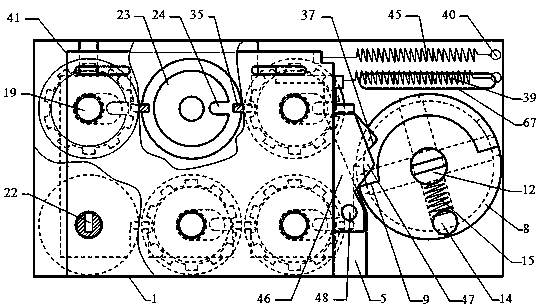
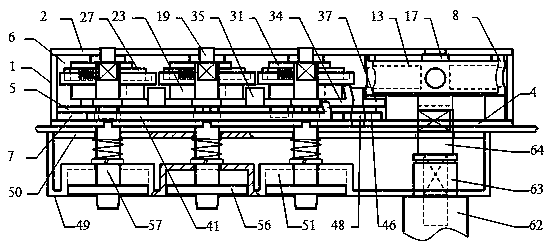
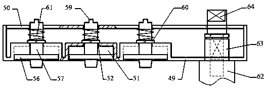
[0063] Such as figure 1 , 2 As shown, the hole-sealing type mechanical combination lock comprises a lock body (1), an outer panel of the lockset (49) and a handle (62), and the inner side of the outer panel of the lockset (49) is assembled with a backplane (50), as image 3 As shown, the backboard (50) is provided with 1 large through hole and 6 small through holes, and the outside of the lockset outer panel (49) is provided with 6 inwardly recessed cylindrical knob shallow holes (51) and 1 Handle mounting holes, an alignment star (not shown in the figure) is provided directly above the shallow holes of each knob, and a central through hole (52) is provided in the center of each shallow hole (51) of each knob, and is respectively connected with the back plate ( 6 small through holes of 50) are concentric, and the large through holes on the handle mounting hole and the back plate (50) are concentric. Six mutually independent knob discs (56), knob shafts (57) and knob springs...
Embodiment approach 2
[0086] The difference from Embodiment 1 lies in that the shape of the swing rod is different, and the connection mode when the swing rod drives the lock bolt to move is different.
[0087] Such as Figure 38 Shown, the end of fork A (72) does not have oblong hole. Such as Figure 40 , 41 , 42, the lock body (1) is provided with a lock bolt driving plate (69), and is positioned at the inner side upper part of the turntable cavity (6), and its right end is provided with a push-pull opening (70), and is connected with the fork A (72 ), the sliding pin (71) is arranged on the left side of the push-pull opening (70). (71) extend out to the outside of the lock body (1) after being movably inserted into the unlocking slideway (67), and a spacer is assembled on the protruding part of the slide pin (71), and its end is provided with an annular groove to assemble a snap ring or 1 The through hole is inserted into the cotter pin. The bottom of the left end of the lock bolt drive pla...
PUM
 Abstract
Description
Claims
Application Information
 - R&D
- Intellectual Property
- Life Sciences
- Materials
- Tech Scout
- Unparalleled Data Quality
- Higher Quality Content
- 60% Fewer Hallucinations
Browse by: Latest US Patents, China's latest patents, Technical Efficacy Thesaurus, Application Domain, Technology Topic, Popular Technical Reports.
© 2025 PatSnap. All rights reserved.Legal|Privacy policy|Modern Slavery Act Transparency Statement|Sitemap|About US| Contact US: help@patsnap.com


