Connecting module and electronic equipment
A technology of modules and connection holes, which is applied in pivot connections, electrical digital data processing, instruments, etc., can solve the problem of not being able to provide enough space to accommodate, and achieve the effect of meeting the requirements of lightness and thinness.
- Summary
- Abstract
- Description
- Claims
- Application Information
AI Technical Summary
Problems solved by technology
Method used
Image

Examples
example 1
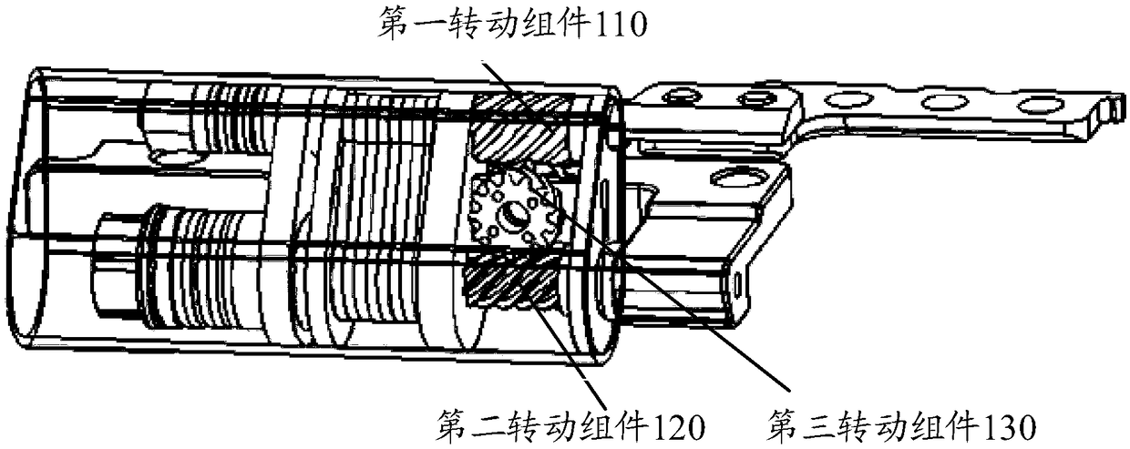
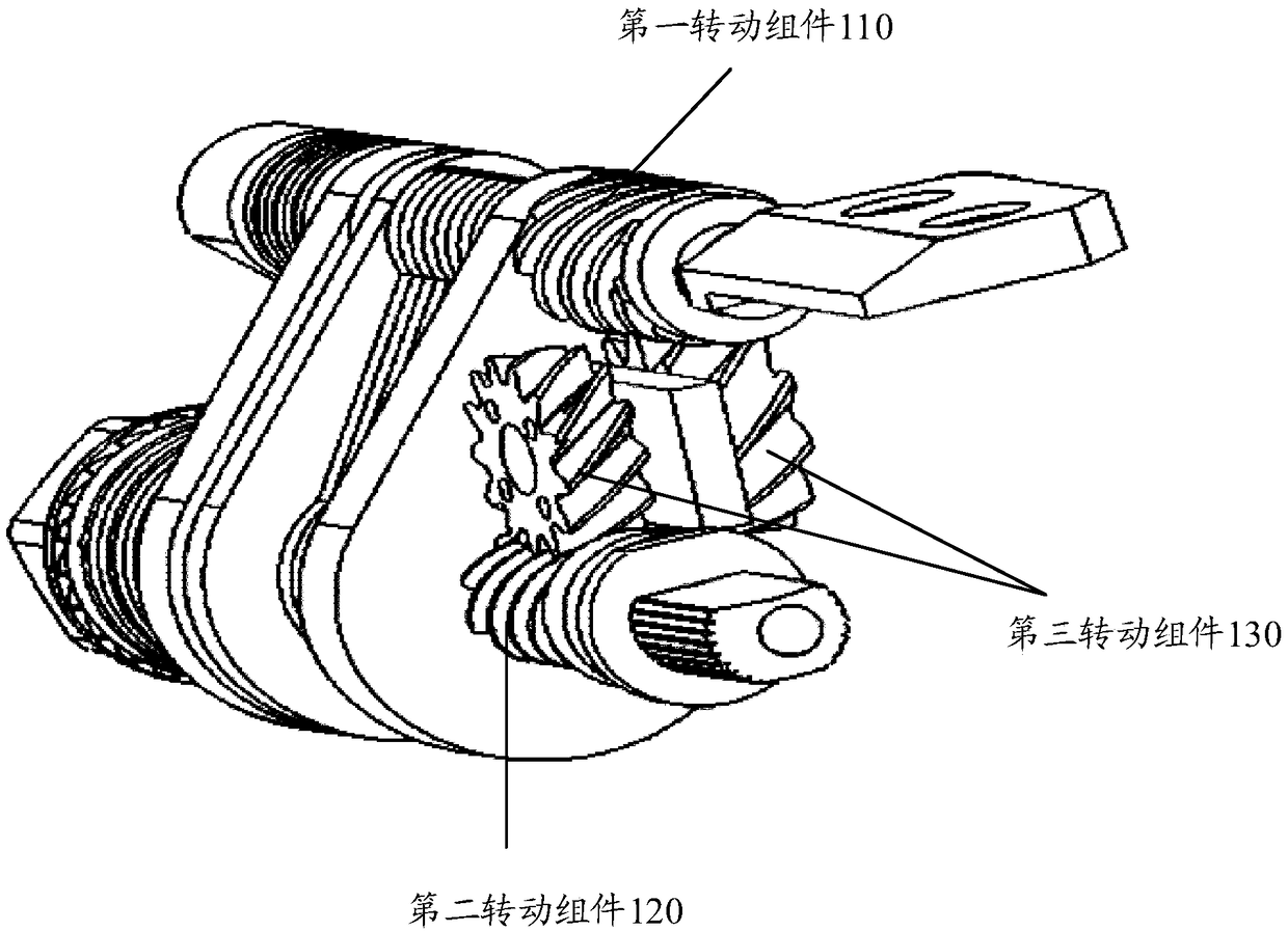
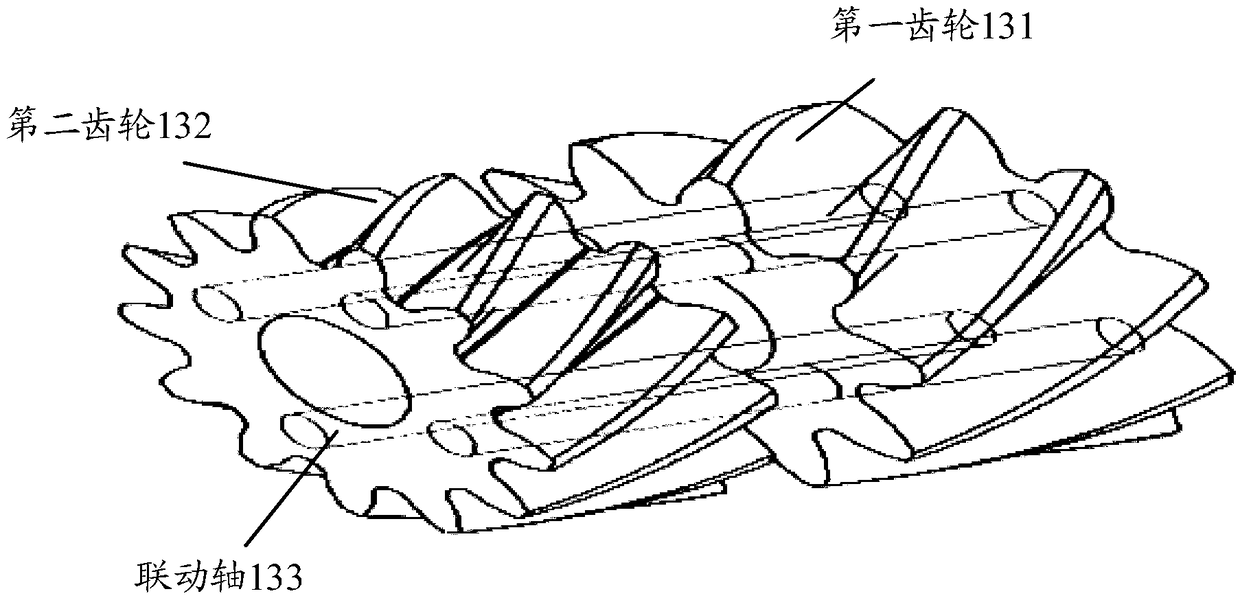
[0137] Figure 5 to Figure 7 A schematic structural diagram of a connection module provided for this example. The intermediate gear is designed with double gears. Because the diameter of the intermediate gear is relatively large, the number of teeth can be adjusted to increase the diameter of the lower shaft gear. The diameter may be the pitch circle diameter. The intermediate gear here can be an integral part of the aforementioned third rotating assembly. Figure 8 and Figure 9 As shown, it is a schematic diagram of the effect after the diameter of the lower shaft gear is increased relative to that of the upper shaft gear.
[0138] The intermediate gear adopts a double gear design and keeps linkage, and the number of teeth is Z2 and Z3 respectively;
[0139] The number of teeth of the upper shaft gear is Z1, and the intermediate gear meshing with the shaft gear is Z2; the upper shaft gear here can be an integral part of the aforementioned first rotating assembly;
[014...
example 2
[0163] This example provides a connection mod such as Figure 8 and Figure 9 As shown, assuming that the connection module is tilted forward by α degrees (the same is true for the backward tilt design), the axis center distance is C, which remains unchanged during the rotation process. The design gap value of LCD and BASE is G in the closed state; the transmission ratio is (180-α) / (180+α);
[0164] Rotation process: LCD rotation angle is 180°-α; BASE rotation angle is 180+α;
[0165] Then there are: under 0 degree closure, the vertical axis center distance is C*cosα;
[0166] Under 360 degrees, the vertical axis center distance is C;
[0167] The increased value of the axial center distance is C-C*cosα=C*(1-cosα);
[0168] Therefore, compared with the 1:1 synchronous design, this solution can increase the accommodation space of the 360-degree foot pad by C*(1-cosα);
[0169] For example: if C=8mm, α=25°, the increased space of this scheme is 0.75mm;
[0170] If the orig...
PUM
 Abstract
Description
Claims
Application Information
 - Generate Ideas
- Intellectual Property
- Life Sciences
- Materials
- Tech Scout
- Unparalleled Data Quality
- Higher Quality Content
- 60% Fewer Hallucinations
Browse by: Latest US Patents, China's latest patents, Technical Efficacy Thesaurus, Application Domain, Technology Topic, Popular Technical Reports.
© 2025 PatSnap. All rights reserved.Legal|Privacy policy|Modern Slavery Act Transparency Statement|Sitemap|About US| Contact US: help@patsnap.com