Overturning plate type electric control valve device

A valve device and flap-type technology, which is applied in the aviation field, can solve the problems of many turns and large flow resistance, and achieve the effects of fewer turns of the flow channel, reduced product weight, and reduced outline size

Pending Publication Date: 2019-03-01
YIBIN SANJIANG MACHINERY
View PDF0 Cites 2 Cited by
  • Summary
  • Abstract
  • Description
  • Claims
  • Application Information

AI Technical Summary

Problems solved by technology

[0003] The purpose of the present invention is to provide a flap-type electric control valve device, which can solve the problem of many turns in the flow channel of the traditional control valve and large flow resistance

Method used


Image

  • Overturning plate type electric control valve device

Examples


Embodiment Construction

[0021] Below in conjunction with accompanying drawing and embodiment the present invention will be further described:

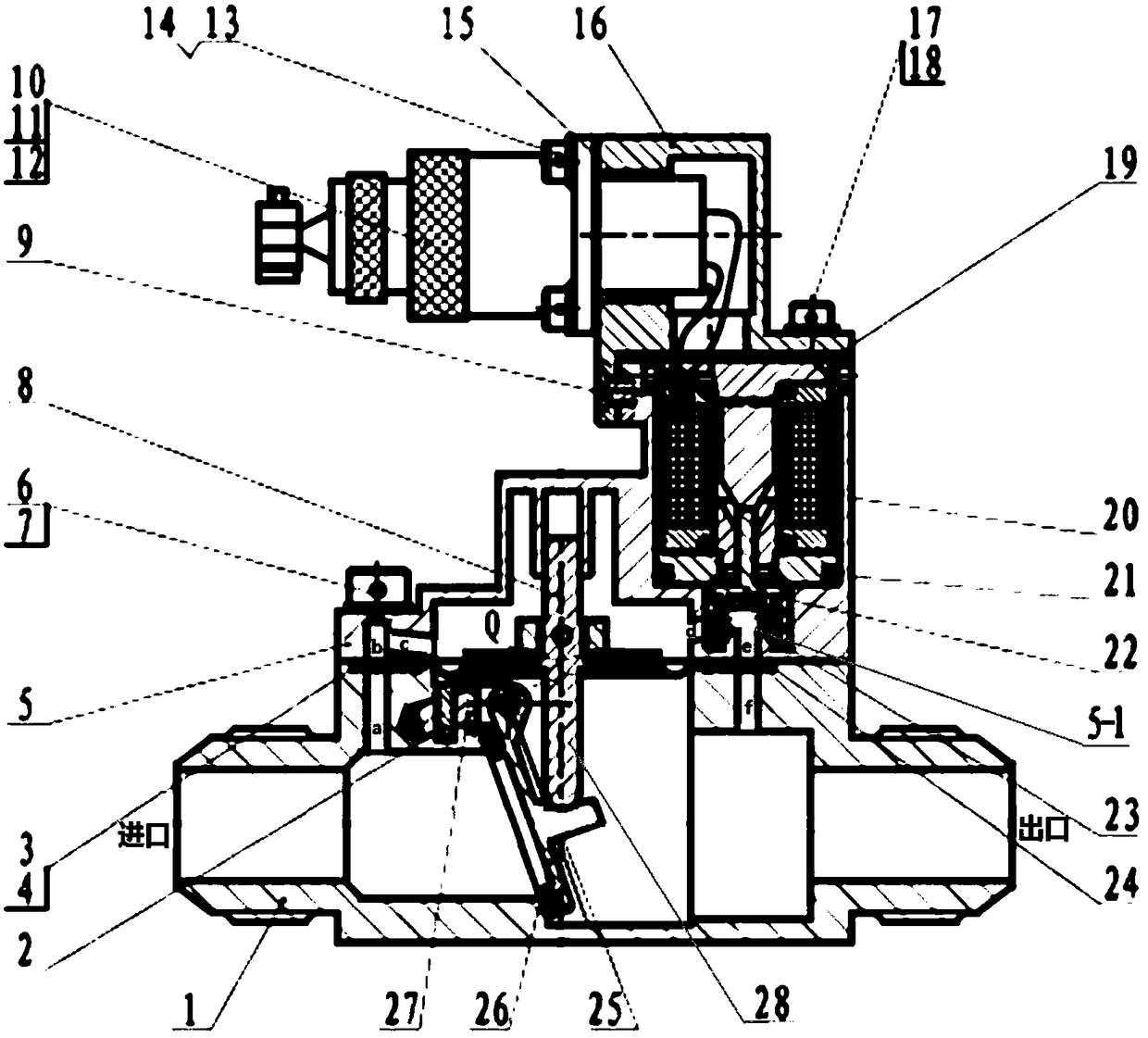
[0022] Such as figure 1 , under normal circumstances, the oil flows into the product from the product inlet. In this state, the small valve assembly 22 is in an open state, and the oil flows from the inlet to the outlet through the a-b-c-d-e-f channel formed by the lower shell 1 and the upper shell 5. The diaphragm assembly 8 The oil in the inner cavity (Q cavity) does not form a force on the valve assembly 26, and the valve assembly 26 is directly opened under the action of the oil pressure, and the oil flows to the outlet through A-B.

[0023] When it is necessary to cut off the oil flowing back to the fuel tank, the product is energized, and the small valve assembly 22 overcomes the elastic force of the spring 23 under the action of the electromagnet 20, and is close to the valve seat 5-1 (the red part in the figure) of the upper casing 5 until the small v...


PUM


Abstract

The invention belongs to the technical field of aviation and relates to an overturning plate type electric control valve device. The device comprises an upper shell, a lower shell, a first oil way anda second oil way, wherein the first oil way and the second oil way are arranged between the upper shell and the lower shell. The first oil way and the second oil way common use the same inlet and thesame outlet. An electromagnetic valve is arranged on the first oil way, and a piston is arranged at the position, between the inlet and the electromagnetic valve, on the first oil way. A valve is arranged on the second oil way. When the electromagnetic valve is electrified, the first oil way is cut off, the piston abuts against the valve, the valve is forced to be closed, and the second oil way is cut off; and when the electromagnetic valve is not electrified, the first oil way is smooth, oil liquid entering the second oil way pushes the valve under the effect of the oil liquid, and thereforethe second oil way can be smooth.

Description

technical field [0001] The invention belongs to the technical field of aviation, and relates to a flap-type electric control valve device. Background technique [0002] The electric control valve is the control device for the fuel flow of the fueling system, and it is a necessary accessory in the fuel system pipeline. The electric control valve is used to cut off the fuel flowing back to the fuel tank. The flap-type electronically controlled valve device solves the problem of the traditional control valve with many turns and large flow resistance, and at the same time further improves the reliability of the electronically controlled valve to cut off and close. Contents of the invention [0003] The purpose of the present invention is to provide a flap-type electric control valve device, which can solve the problem of many turns in the flow channel of the traditional control valve and large flow resistance. [0004] In order to solve the problems of the technologies descri...

Claims


Application Information

Patent Timeline
Patent Type & Authority Applications(China)
IPC IPC(8): F16K1/18F16K31/42
CPCF16K1/18F16K31/42
Inventor 曾林
Owner YIBIN SANJIANG MACHINERY
Why Eureka
Try Eureka