Flame piece suspended electronic candle lamp

An electronic candle and flame plate technology, applied in the field of lighting, can solve the problems of poor flame swing effect, small swing range of the flame plate, and unsmooth swing, and achieve the effect of stable swing and improving the effect of the flame swinging back and forth.

Pending Publication Date: 2019-03-01
SHENZHEN TONGFANG OPTOELECTRONICS TECH
View PDF0 Cites 4 Cited by
  • Summary
  • Abstract
  • Description
  • Claims
  • Application Information

AI Technical Summary

Problems solved by technology

[0002] At present, the flame sheet of the traditional electronic candle lamp is suspended on the bracket for swinging. The swing range of the flame sheet of this structure is small and the swing is not smooth, which leads to poor flame swing effect when simulating candle burning.

Method used


Image

  • Flame piece suspended electronic candle lamp
  • Flame piece suspended electronic candle lamp
  • Flame piece suspended electronic candle lamp

Examples


Embodiment 1

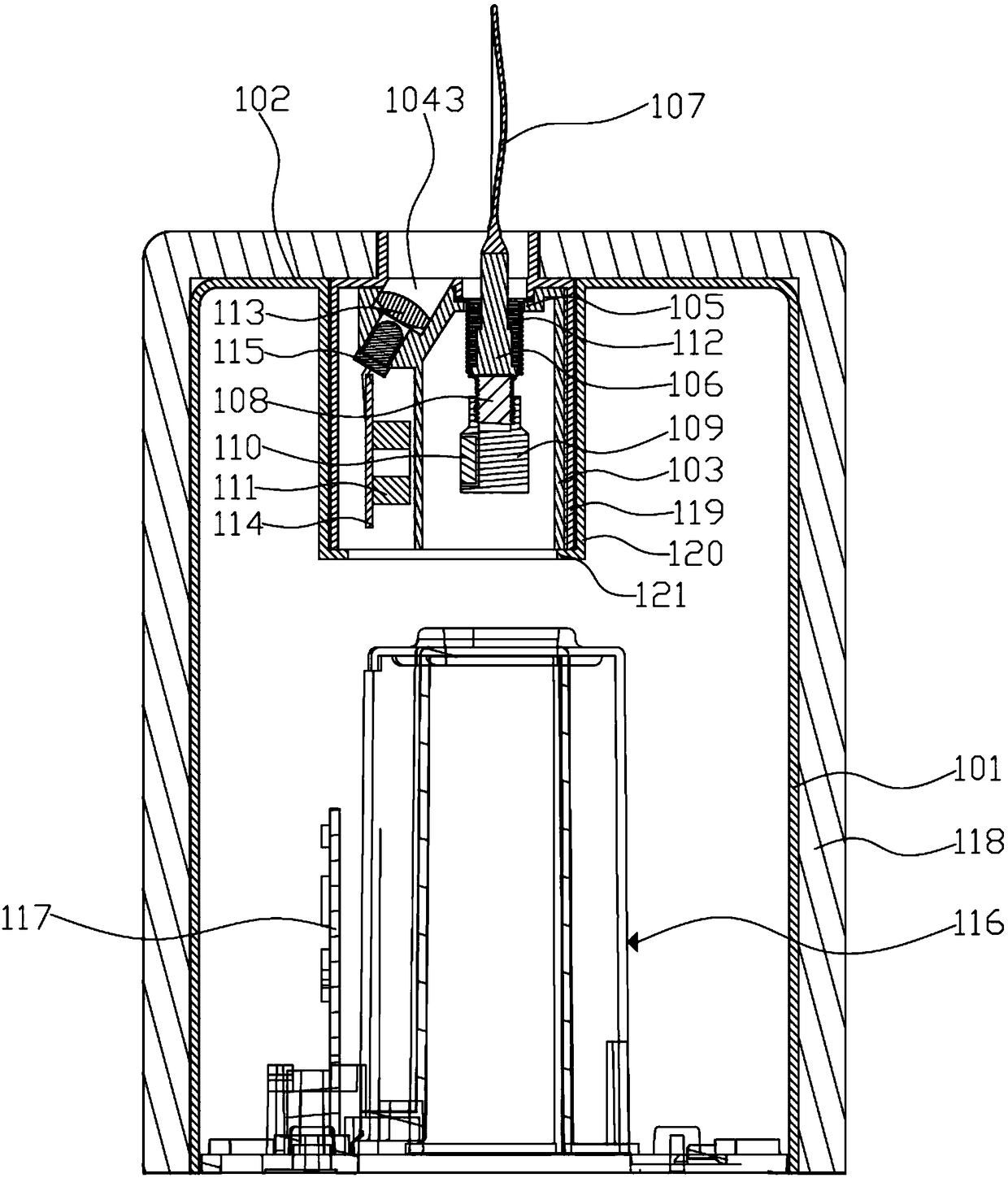
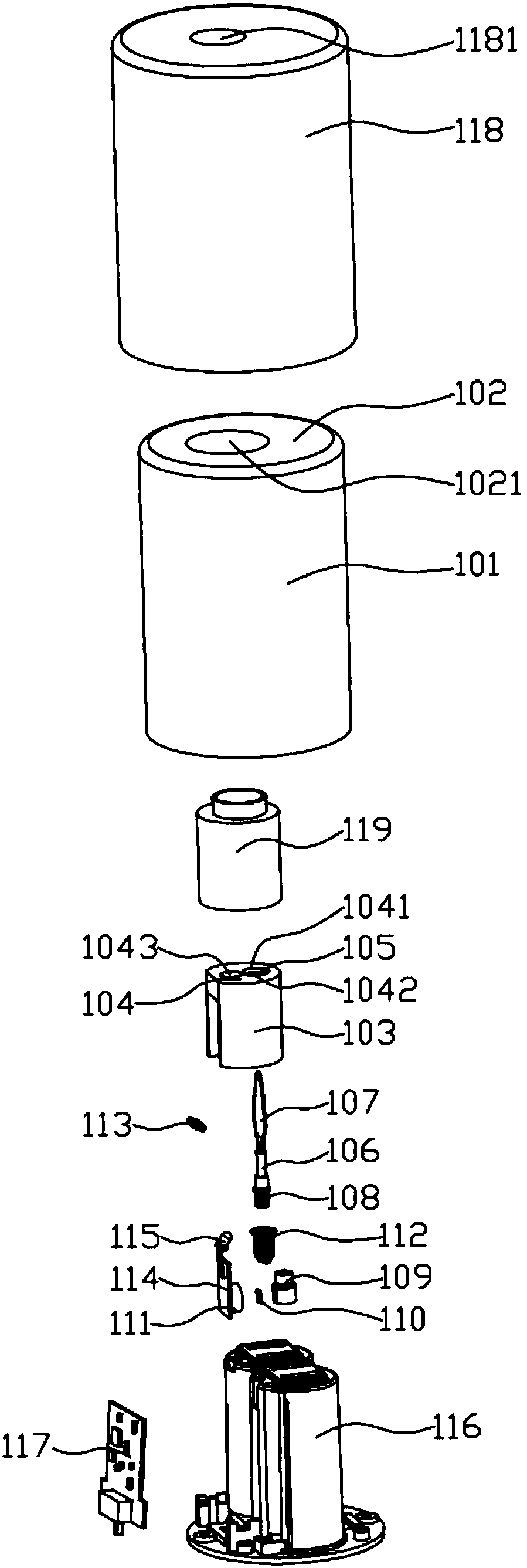
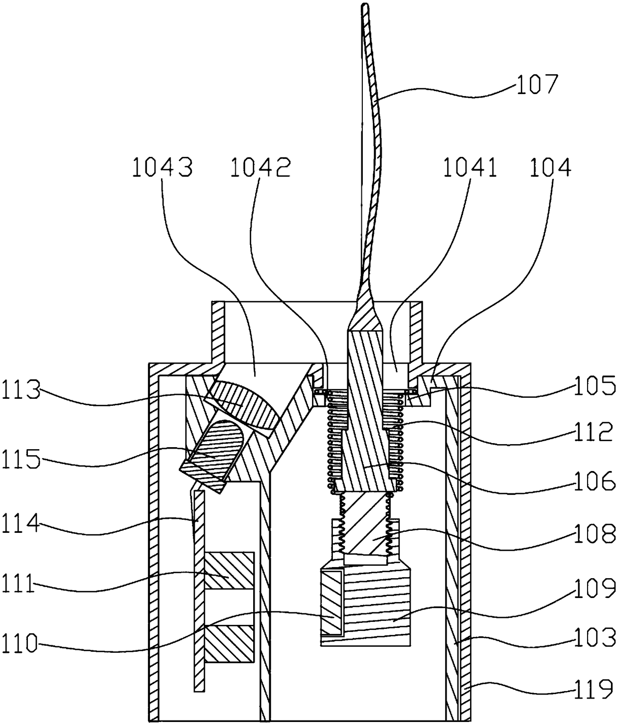
[0037] Such as Figure 1-Figure 5As shown, a flame sheet suspended electronic candle lamp provided by Embodiment 1 of the present invention includes a vertically arranged inner cylinder 101, a flat plate 102 is fixed on the top of the inner cylinder 101, and the bottom of the inner cylinder 101 is open. There is a first through hole 1021, and the first through hole 1021 is fixed with a vertical installation cylinder 103 located in the inner cylinder 101. The top of the installation cylinder 103 is fixed with a installation plate 104, the bottom of the installation cylinder 103 is open, and the installation plate 104 There are a first installation hole 1041 and a second installation hole 1042 which are communicated in sequence from top to bottom. The first installation hole 1041 and the second installation hole 1042 are arranged coaxially. The diameter of the first installation hole 1041 is larger than that of the second installation hole. The diameter of the hole 1042, an annu...

Embodiment 2

[0051] Such as Figure 6-Figure 10 As shown, a flame sheet suspended electronic candle lamp provided by Embodiment 2 of the present invention includes a vertically arranged inner cylinder 201, a flat plate 202 is fixed on the top of the inner cylinder 201, the bottom of the inner cylinder 201 is open, and a There is a first through hole 2021, and the first through hole 2021 is fixed with a vertically installed installation cylinder 203 located in the inner cylinder 201. The top of the installation cylinder 203 is fixed with a installation plate 204, the bottom of the installation cylinder 203 is open, and the installation plate 204 There are a first installation hole 2041 and a second installation hole 2042 connected in sequence from top to bottom. The first installation hole 2041 and the second installation hole 2042 are arranged coaxially. The diameter of the first installation hole 2041 is larger than that of the second installation hole. The diameter of the hole 2042, an a...


PUM


Abstract

The invention discloses a flame piece suspended electronic candle lamp. The flame piece suspended electronic candle lamp comprises an inner cylinder, a flat plate, a mounting cylinder, a mounting plate, a connecting rod, a flame piece, a screw rod, a pendulum bob, a magnet, an electromagnetic coil, a first fixed plate, a spring, an LED lamp, a convex lens, a power supply control board and a battery set. The spring alternately stores and releases elastic potential energy in the swinging process with the connecting rod, the flame piece, the screw rod, the pendulum bob and the magnet; when the spring releases the elastic potential energy, the swinging amplitude with the connecting rod, the flame piece, the screw rod, the pendulum bob and the magnet is increased, and the connecting rod, the flame piece, the screw rod, the pendulum bob and the magnet swing more smoothly, so that the flame piece preferably simulates a flame reciprocating swinging effect during combusting of a candle; the pendulum bob is suspended under the spring through the screw rod; and the gravity center of a structure formed by the connecting rod, the flame piece, the screw rod, the pendulum bob and the magnet can be located on the pendulum bob, so that the connecting rod, the flame piece, the screw rod, the pendulum bob and the magnet swing more stably.

Description

technical field [0001] The invention belongs to the field of lighting, in particular to a flame sheet suspended electronic candle lamp. Background technique [0002] At present, the flame sheet of the traditional electronic candle lamp is hung on the support for swinging. The swing range of the flame sheet of this structure is small and the swing is not smooth, which leads to poor effect of flame swing when simulating candle burning. Contents of the invention [0003] The object of the present invention is to overcome the shortcomings of the above-mentioned prior art, and provide a flame sheet suspended electronic candle lamp. [0004] The present invention is a kind of flame sheet suspended electronic candle lamp, which includes a vertically arranged inner cylinder, a flat plate is fixed on the top of the inner cylinder, the bottom of the inner cylinder is open, and a first A through hole, the first through hole is fixed with a vertically installed installation cylinder ...

Claims


Application Information

Patent Timeline
Patent Type & Authority Applications(China)
IPC IPC(8): F21S10/04F21S9/02F21V19/00F21V15/01F21V23/00F21Y115/10
CPCF21S10/046F21S9/02F21V15/01F21V19/001F21V23/003F21Y2115/10
Inventor 范宝生崔华明
Owner SHENZHEN TONGFANG OPTOELECTRONICS TECH
Why Eureka
Try Eureka