Gas shielded welding oscillator with welding joint tracing function
A technology of gas shielding and welding oscillator, which is applied in the direction of manufacturing tools, welding rod characteristics, welding equipment, etc., can solve the problems of inability to detect processing errors in real time, assembly errors, welding heat deformation, weld seam gaps, etc., and achieve intelligent welding and compensation The effect of excessive welding seam gap and improving welding quality and efficiency
- Summary
- Abstract
- Description
- Claims
- Application Information
AI Technical Summary
Problems solved by technology
Method used
Image
Examples
Embodiment 1
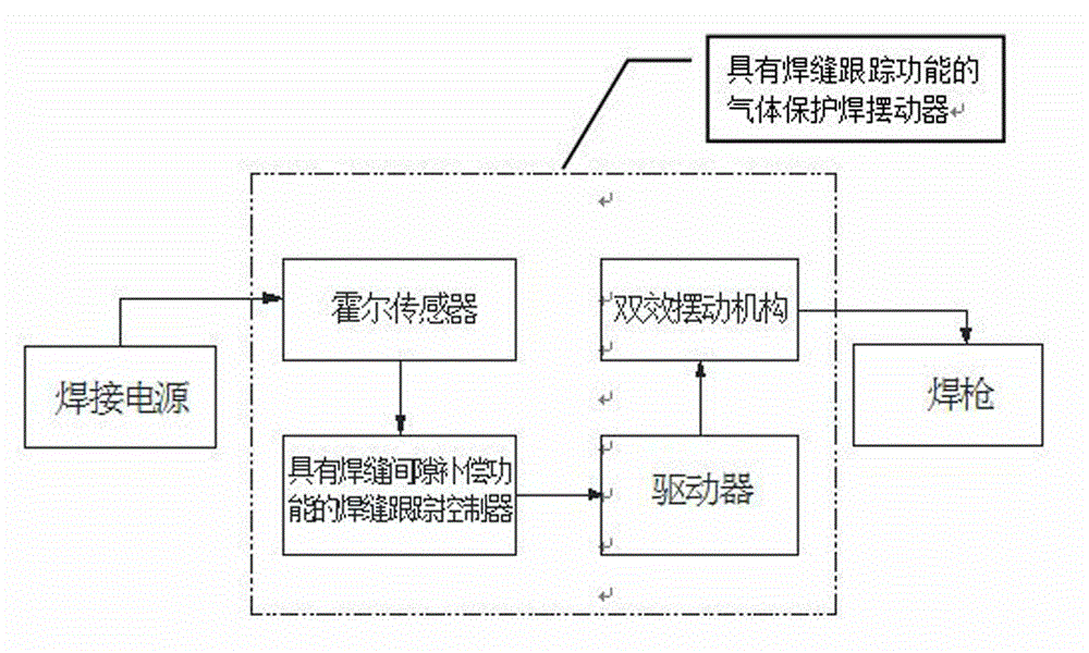
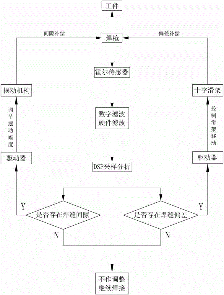
[0034]Embodiment 1, the present invention includes a Hall sensor, a weld seam tracking controller with weld seam gap compensation, a driver and a double-effect swing mechanism, and the weld seam tracking controller detects and compensates in real time according to the signal collected by the Hall sensor and compensates for workpiece processing errors. , Assembly errors and weld gaps caused by thermal deformation of welding, under the control of electrical control and driver, the double-effect swing mechanism can freely transform between horizontal pendulum and pendulum and automatically adjust the swing amplitude and swing frequency. refer to Figure 1 to Figure 8 .
Embodiment 2
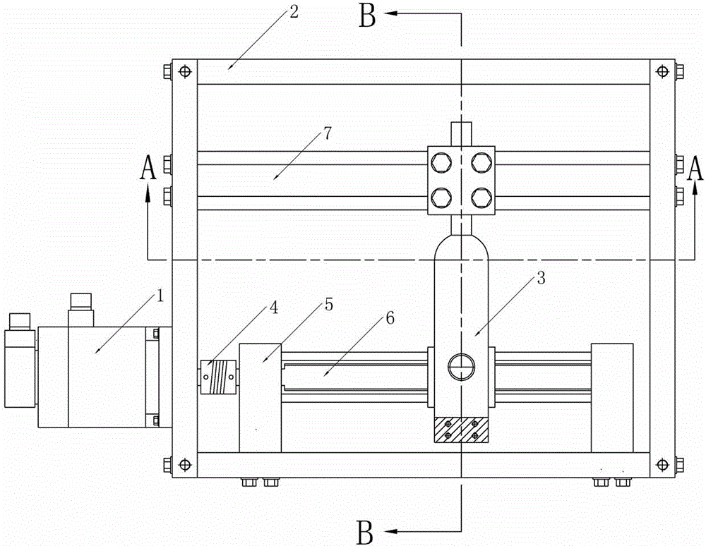
[0035] Embodiment 2, the double-effect swing mechanism includes a housing 2, the housing 2 is provided with a lead screw 6 connected to the servo motor 1 outside the housing 2 through a coupling 4, and the main slider 9 is set on the lead screw 6, The electromagnetic clutch Ⅰ10 is fixed in the main slider 9, and the chute 7 fixed on the housing 2 is arranged in parallel above the lead screw 6. The slave slider 13 can move in parallel in the chute 7, and the electromagnetic clutch Ⅱ15 is fixed on the sliding chute by screws. At the middle position of the groove 7, a guide rod 3 is vertically arranged between the lead screw 6 and the chute 7, the contact surface between the lower end of the guide rod 3 and the electromagnetic clutch I10 and the contact surface between the upper end of the guide rod 3 and the electromagnetic clutch II15 are smooth Magnetic surface. refer to Figure 1 to Figure 8 , all the other are with embodiment 1.
Embodiment 3
[0036] Embodiment 3, housing 2 bottoms are symmetrically fixedly installed with two supports 5, and the two ends of leading screw 6 and guide rail 8 are installed on two supports 5, and bearing is housed in support 5, and leading screw 6 can rotate in support 5. refer to Figure 1 to Figure 8 , and the rest are the same as the above-mentioned embodiment.
PUM
 Abstract
Description
Claims
Application Information
 - R&D
- Intellectual Property
- Life Sciences
- Materials
- Tech Scout
- Unparalleled Data Quality
- Higher Quality Content
- 60% Fewer Hallucinations
Browse by: Latest US Patents, China's latest patents, Technical Efficacy Thesaurus, Application Domain, Technology Topic, Popular Technical Reports.
© 2025 PatSnap. All rights reserved.Legal|Privacy policy|Modern Slavery Act Transparency Statement|Sitemap|About US| Contact US: help@patsnap.com


