Retaining wall

Active Publication Date: 2012-03-29
LES MATERIAUX DE CONSTR OLDCASTLE CANADA
View PDF17 Cites 25 Cited by
  • Summary
  • Abstract
  • Description
  • Claims
  • Application Information

AI Technical Summary

Benefits of technology

[0025]The wall in accordance with the invention can be built in situ, and preferably uses only the facing and backer blocks as wall components and their connectors. The connectors are preferably constructed with multiple connecting ends to engage at least a pair of blocks in a back-to-back arrangement. The connecting ends can be joined by interconnecting webs. The connectors are dimensioned to occupy as little as possible of the space between the back-to-back block walls to thereby maximize the amount of fill which can be placed in the space between the back-to-back blocks. The connectors are preferably constructed of a material which provides sufficient flexibility for interlocking engagement of the connectors with the blocks, even when the connector is not perfectly aligned with the complementary retaining structure in the block, while resisting longitudinal extension. Thus, the connectors are preferably flexible but non-extendible.
[0026]The wall of the present application can be assembled straight or curved. Curved hollow walls made of a pair of spaced apart parallel wall portions, provide the additional challenge that due to the curvature of the wall, the outer portion wall is longer than the inner portion wall, which leads to a mismatching of the blocks in the inner and outer portion wall of the curved hollow wall. Moreover, maintaining the inner and outer portion wall continuous is important for avoiding loss of the loose fill. Misalignment of the facing and backer wall portions in a curved wall also creates challenges with interconnecting the facing and backer wall portions, since the retaining structures in respectively opposing blocks are no longer aligned. This problem is addressed by providing one of the facing and backer blocks with retaining structures spaced apart by one pitch (1W), to a

Problems solved by technology

Although that system is very flexible, since the retaining wall can be provided with many different facing surfaces, which can even be exchanged without dismantling the wall, the base blocks suffer from the same drawbacks as other known retaining wall blocks.
Local building code requirements dictate the forces such walls must be able to withstand, which in turn limit the design possibilities in terms of maximum wall heights for a given width and mass of a wall.
This in turn limits the maximum length and height of retaining wall blocks useful for manual installation.
It also limits the overall retaining capacity achieva

Method used


Image

  • Retaining wall
  • Retaining wall
  • Retaining wall

Examples


Embodiment Construction

[0056]Before explaining the present invention in detail, it is to be understood that the invention is not limited to the preferred embodiments contained herein. The invention is capable of other embodiments and of being practiced or carried out in a variety of ways. It is to be understood that the phraseology and terminology employed herein are for the purpose of description and not of limitation.

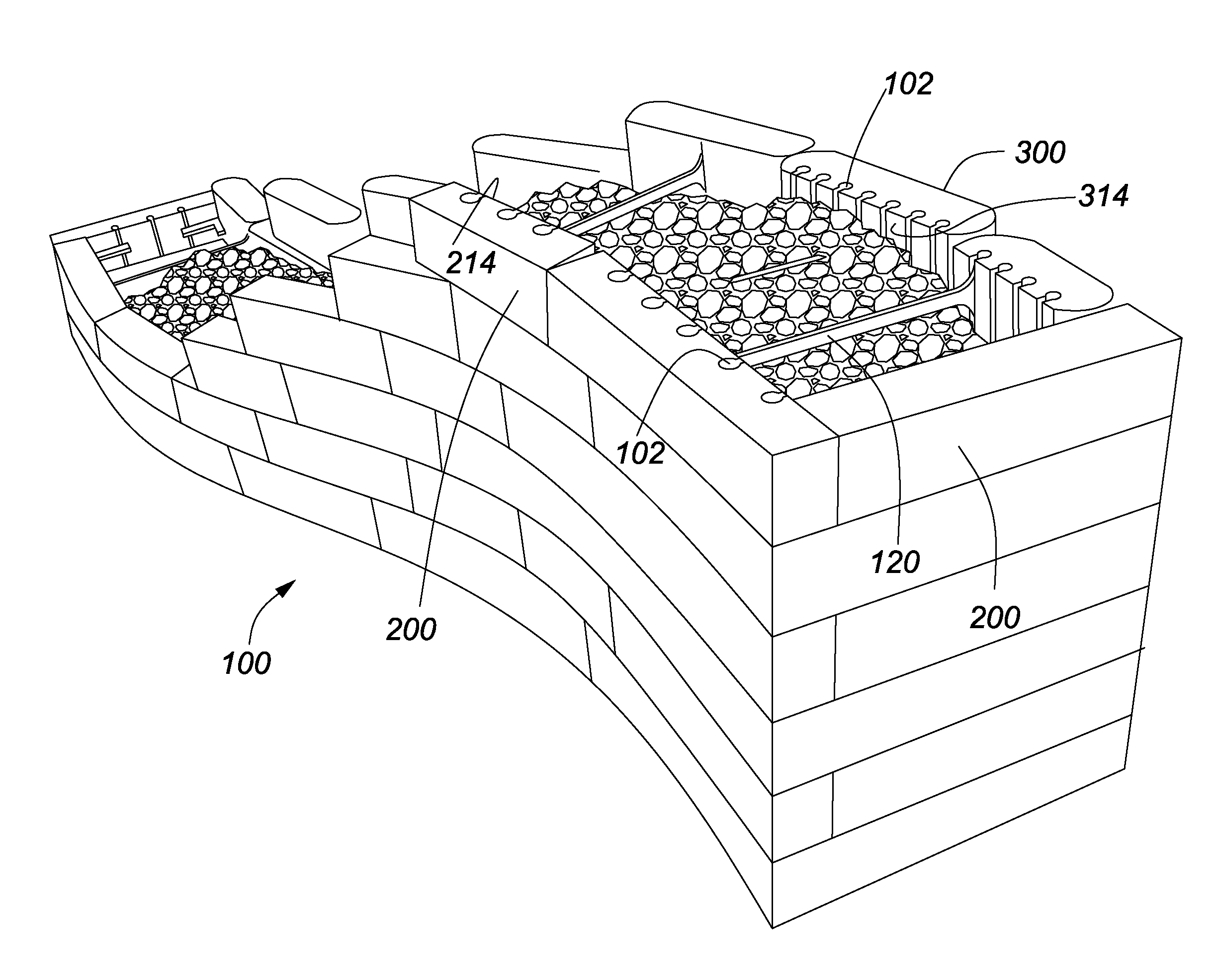
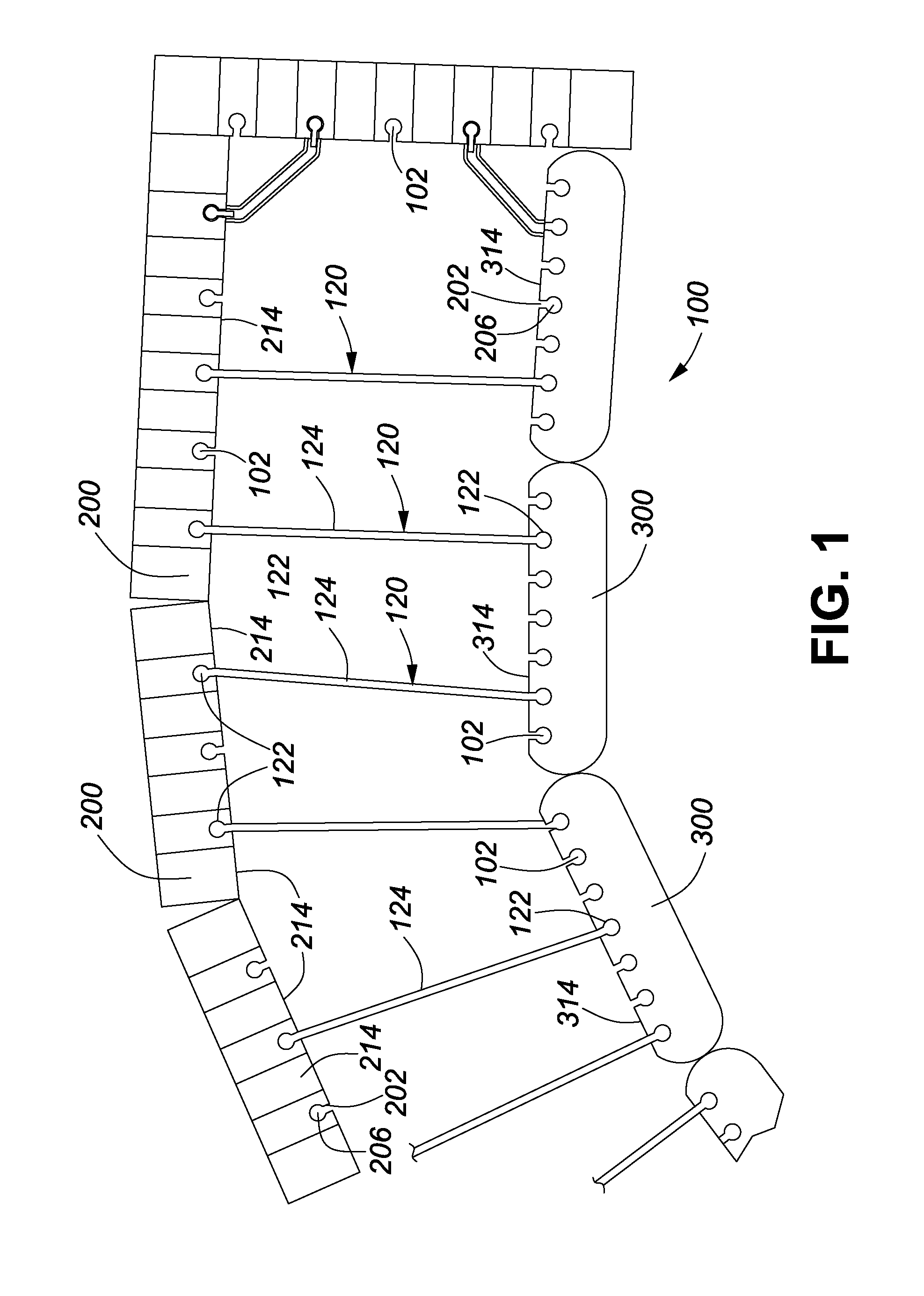
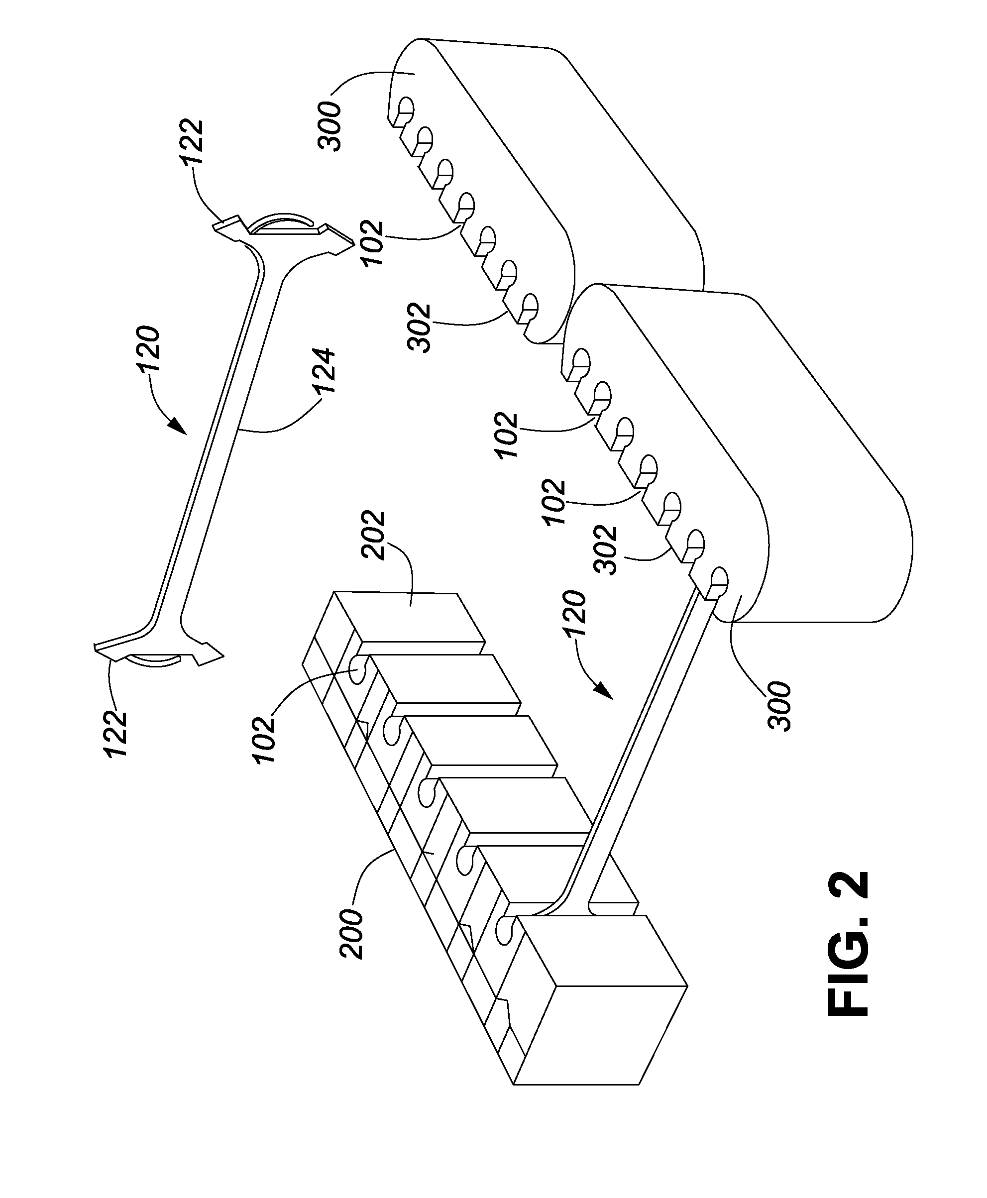
[0057]FIG. 1 and FIGS. 6a to 6e illustrate the method in accordance with the invention of constructing a modular wall 100, such as a retaining wall, by connecting pairs of wall blocks, namely facing blocks 200 and backer blocks 300 in a back-to-back arrangement with an intermediate space filled with a filler material 500. The facing blocks 200 have a decorative surface 210, in the illustrated embodiment. Each facing block 200 is connected by way of connectors 120, with at least one backer block. The facing blocks 200 and backer blocks 300 in the illustrated embodiment have rear faces 214 an...


PUM


Abstract

Disclosed is an economical and effective way of producing a modular retaining wall, using only blocks which in and of themselves are of insufficient thickness to function as retaining wall blocks. The modular wall includes backer blocks and facing blocks which are connected by connectors in a back to back, spaced apart arrangement, thereby forming a hollow retaining wall. The hollow wall can be filled with loose filler material to increase the mass and retaining capacity of the wall. Further disclosed are wall components and a wall kit for a modular retaining wall. A double sided decorative wall is also disclosed. The modular wall system allows for the construction of retaining walls and freestanding, double sided, decorative walls forming both straight and curved walls.

Description

CROSS REFERENCE TO RELATED APPLICATIONS[0001]This application claims the benefit of priority of U.S. Provisional Patent Application No. 61 / 387,222 filed Sep. 28, 2010, and U.S. Patent Application No. 61 / 420,890 filed Dec. 8, 2010, both of which are incorporated herein by reference in their entirety.FIELD OF THE INVENTION[0002]The present invention is generally directed toward retaining walls and freestanding walls. In particular, the invention is directed to modular retaining walls and to components of such walls.BACKGROUND OF THE INVENTION[0003]Retaining walls are used in landscaping around residential or commercial buildings. Retaining walls can be made of various materials, but for reasons of durability are most often either concrete structures cast in situ or walls formed of stacked courses of natural stone or masonry blocks. Concrete masonry blocks have become the most popular retaining wall components, due to their ease of manufacture, transport and handling. The blocks are st...

Claims


Application Information

Patent Timeline
IPC IPC(8): E04B2/34E04G21/14E04B2/30
CPCE02D29/0225E02D29/0233E04B2/8641E04C1/395E04B2002/867E04B2002/8676E04B2002/0247
Inventor CASTONGUAY, BERTINLACAS, MARC-ANDREDAOUST, ROBERT
Owner LES MATERIAUX DE CONSTR OLDCASTLE CANADA
Why Eureka
Try Eureka