Method for detecting the number of fallen particles during working process of valve

A working process, particle counter technology, applied in measurement devices, mechanical valve testing, individual particle analysis, etc., can solve problems such as the quality of semiconductor or photovoltaic modules, and achieve the effect of easy operation and simple detection principle

Active Publication Date: 2019-03-01
SICHUAN JIUTIAN VACUUM TECH CO LTD +1
View PDF9 Cites 1 Cited by
  • Summary
  • Abstract
  • Description
  • Claims
  • Application Information

AI Technical Summary

Problems solved by technology

[0003] The purpose of the present invention is to provide a method for detecting the amount of particle shedding during the valve working process, by which the amount of particle falling off during the valve working process can be detected, so that the manufacturer and purchaser of the valve can accurately understand the particle shedding amount of the valve data, which solves the problem that the quality of semiconductors or photovoltaic modules is affected due to the particle shedding of the valve not meeting the requirements

Method used


Image

  • Method for detecting the number of fallen particles during working process of valve
  • Method for detecting the number of fallen particles during working process of valve
  • Method for detecting the number of fallen particles during working process of valve

Examples


Embodiment 1

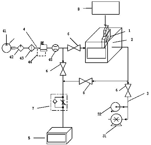
[0058] The method for detecting the number of particles falling off during the working process of the valve provided in this embodiment is specifically (for the convenience of illustration, combined with figure 1 Be explained):

[0059] Step 1: Connect the gas inlet device 4, the vacuum device 3 and the particle counter 5 on the cavity 2, insert the valve 1 to be tested into the cavity 2, connect the valve 1 to be tested to the valve driving device 8 to be tested, and the valve to be tested The driving device 8 drives the valve 1 to be tested to open and close; the valve I6 is installed on the connecting pipeline between the gas inlet device 4 and the cavity, and the valve II61 is installed on the pipeline connecting the gas inlet device 4 and the particle counter 5. 5. Install valve Ⅲ62 on the pipeline connected to cavity 2, and install valve Ⅳ63 on the pipeline connected to vacuum device 3 and the cavity; first close valve Ⅰ6, valve Ⅱ61, valve Ⅲ62, open valve Ⅳ63, and contro...

Embodiment 2

[0064] This embodiment is basically the same as Embodiment 1, except that the gas is introduced into the cavity through the gas inlet device first, and then the gas enters the cavity and then enters the particle counter 5 for counting, records the number a1 displayed by the particle counter, and then After clearing the particle counter 5, pass the gas of the same flow rate into the particle counter 5 that has been reset to count through the gas inlet device, record the number b1 displayed by the particle counter, and calculate the number of particles falling off c1=a1-b1 .

Embodiment 3

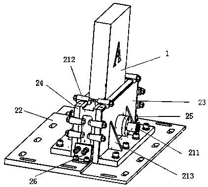
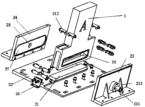
[0066] This embodiment is basically the same as Embodiment 1, except that the structure of the cavity is further limited in this embodiment, and the specific structure of the cavity 2 is as follows: the cavity 2 includes a bottom plate 22, a fixing splint flange 23, Movable splint flange 24, positioning block 25 and movable clamping device 26, fixed splint flange 23, movable splint flange 24, positioning block 25 and movable clamping device 26 are fixed on the base plate 22, fixed splint flange 23 and movable clamping device The splint flange 24 is close to the valve to be tested 1 ( figure 2 The housing of the valve to be tested is illustrated in the figure, and the internal structure diagram is not drawn for simplicity) The positive and negative sides (sides A and B in the figure) realize the fixing of the positive and negative sides of the valve to be tested 1, the positioning block 25 and the movable clamp The tightening device 26 is close to the both sides of the valve 1...


PUM


Abstract

The invention discloses a method for detecting the number of fallen particles during the working process of a valve. The method comprises firstly making a cavity vacuum; then opening and closing the valve until the number of opening and closing times of the valve reaches the actual working number of times of the valve to be tested, wherein the particles fallen during the working process of the valve fall into the cavity; then counting the fallen particles by a particle counter, wherein the calculation principle of the particle counter is to blown the fallen particles into the particle counterby a gas, then to blow a gas of the same flow into the particle counter, and to compare the two numbers so as to obtain the number of the fallen particles. The method can detect the number of fallen particles during the working process of the valve, so that a manufacturer and a purchaser of the vacuum valve can accurately understand the number of the fallen particles of the vacuum valve, thereby solving the problem that the quality of a semiconductor or photovoltaic module is affected because the number of the fallen particles of the vacuum valve does not meet a requirement.

Description

technical field [0001] The invention relates to a method for detecting a valve, in particular to a method for detecting the quantity of particles falling off during the working process of the valve. Background technique [0002] Vacuum valves are used in the manufacturing of semiconductors and photovoltaic modules. Due to the very high requirements for vacuum valves in the manufacturing process of semiconductors and photovoltaic modules, in addition to some conventional requirements (such as size, sealing, impact resistance, etc.), there are also certain requirements for the amount of particles shed by vacuum valves during work. , if the amount of particle shedding is large, it will affect the quality of the entire semiconductor and photovoltaic modules. Therefore, it is necessary to detect the particle shedding amount of the vacuum valve, but there is no prior art for detecting the particle shedding amount of the vacuum valve at present. Due to the lack of relevant detect...

Claims


Application Information

Patent Timeline
Patent Type & Authority Applications(China)
IPC IPC(8): G01M13/003G01N15/10
CPCG01M13/00G01N15/10G01N2015/1062
Inventor 靳毅孙围华刘绘生余健王丛岭蒋丹宋敏陈泽芸
Owner SICHUAN JIUTIAN VACUUM TECH CO LTD
Why Eureka
Try Eureka