Heat dissipation structure of server

A server and heat dissipation technology, which is applied in the direction of instruments, electrical digital data processing, digital data processing components, etc., can solve the problems of increasing costs, ineffective use of limited space, increasing the density of internal components in the chassis, etc., to increase contact area, improve the effect of heat dissipation, and improve the effect of heat dissipation efficiency

Inactive Publication Date: 2019-03-01
ZHENGZHOU YUNHAI INFORMATION TECH CO LTD
View PDF5 Cites 1 Cited by
  • Summary
  • Abstract
  • Description
  • Claims
  • Application Information

AI Technical Summary

Problems solved by technology

However, this method cannot effectively utilize the limited space inside the server chassis, increases the density of components inside the chassis, and also increases the cost.

Method used


Image

  • Heat dissipation structure of server
  • Heat dissipation structure of server
  • Heat dissipation structure of server

Examples


Embodiment

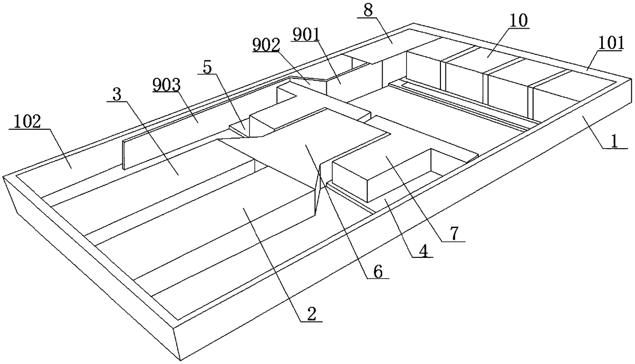
[0030] In the case of a 2U server, such as figure 1 As shown, it includes a power supply 8, two FPGA cards and two CPUs, the power supply 8, two FPGA cards and two CPUs are all connected to the chassis bottom plate, and the two FPGA cards are respectively the first FPGA card 2 and the second FPGA card 3 , the first FPGA card 2 and the second FPGA card 3 are all located at the left end of the chassis 1, the heat dissipation end of the first FPGA card 2 and the heat dissipation end of the second FPGA card 3 are opposite to the air outlet of the chassis, and the air outlet of the chassis is located in the chassis On the right side wall 101, two CPUs are respectively the first CPU4 and the second CPU5, and the first CPU4 is arranged on the right side of the heat dissipation end of the first FPGA card 2, and the second CPU5 is located on the right side of the heat dissipation end of the second FPGA card 3 , there are four fan modules 10 arranged side by side in the chassis 1, and t...


PUM


Abstract

A heat dissipation structure of a server the invention relates to the technical field of server heat dissipation architecture, including power, FPGA card and CPU, FPGA card is arranged at that left end of the chassis, the heat dissipation end of the FPGA card is opposite to the air outlet of the chassis. A chassis air outlet is arranged on the right side wall of the chassis, the right end of the FPGA card is provided with an air guide cover, the air deflector comprises a first air deflector and a second air deflector sequentially connected from left to right. The left end of the first air guide cover is connected with the heat dissipation end of the FPGA card, the end of the second air guide cover away from the first air guide cover is opposite to the air outlet of the chassis, and the CPUis arranged on the front side or the rear side of the air guide cover. The inner cavity of the first air guide cover is a trumpet shape with a large left end and a small right end. The invention caneffectively utilize the limited space inside the server chassis to guide the hot air generated by the FPGA card, improve the heat dissipation effect of the components inside the chassis, reduce the density of the components inside the chassis and reduce the cost.

Description

technical field [0001] The present invention relates to the technical field of server heat dissipation architecture, in particular to a server heat dissipation architecture. Background technique [0002] With the development of new technologies such as cloud computing and big data, the internal components of the server chassis are getting closer and closer, and the computing speed and amount of computing of the processor are also increasing. The memory, hard disk, CPU, FPGA card and other components heat production also increased. [0003] In a server chassis including a power supply, FPGA card and CPU, the FPGA card is located at the left end of the chassis, the cooling end of the FPGA card is opposite to the air outlet of the chassis, the air outlet of the chassis is located on the right side wall of the chassis, and the CPU is located at the heat dissipation area of ​​the FPGA card. to the right of the end. Therefore, the hot air generated by the FPGA card will flow thr...

Claims


Application Information

Patent Timeline
Patent Type & Authority Applications(China)
IPC IPC(8): G06F1/20
CPCG06F1/20
Inventor 宗斌
Owner ZHENGZHOU YUNHAI INFORMATION TECH CO LTD
Why Eureka
Try Eureka