Intelligent constant-temperature dehumidification device

A constant temperature dehumidification and intelligent technology, applied in lighting and heating equipment, heating methods, applications, etc., can solve problems such as humidity, affecting power usage, and damage to equipment in the station, and achieve the effect of avoiding excessively high or low temperature

Inactive Publication Date: 2020-01-17
徐州瓦特电气科技有限公司
View PDF12 Cites 12 Cited by
  • Summary
  • Abstract
  • Description
  • Claims
  • Application Information

AI Technical Summary

Problems solved by technology

[0002] The smart substation adopts advanced, reliable, integrated and environmentally friendly smart equipment, with the basic requirements of digitalization of the whole station information, networked communication platform, and standardized information sharing, and automatically completes basic functions such as information collection, measurement, and control. At the same time, it has the ability to support power grids For substations with advanced functions such as real-time automatic control, intelligent adjustment, online analysis and decision-making, and collaborative interaction, the equipment inside the smart substation is in a live running state, and the requirements for humidity are high, and the indoors of the substation are relatively humid during rainy seasons, which may It will lead to damage or short circuit of the equipment in the station, which may seriously cause a power outage of the entire station and affect the use of electricity

Method used


Image

  • Intelligent constant-temperature dehumidification device
  • Intelligent constant-temperature dehumidification device
  • Intelligent constant-temperature dehumidification device

Examples


Embodiment

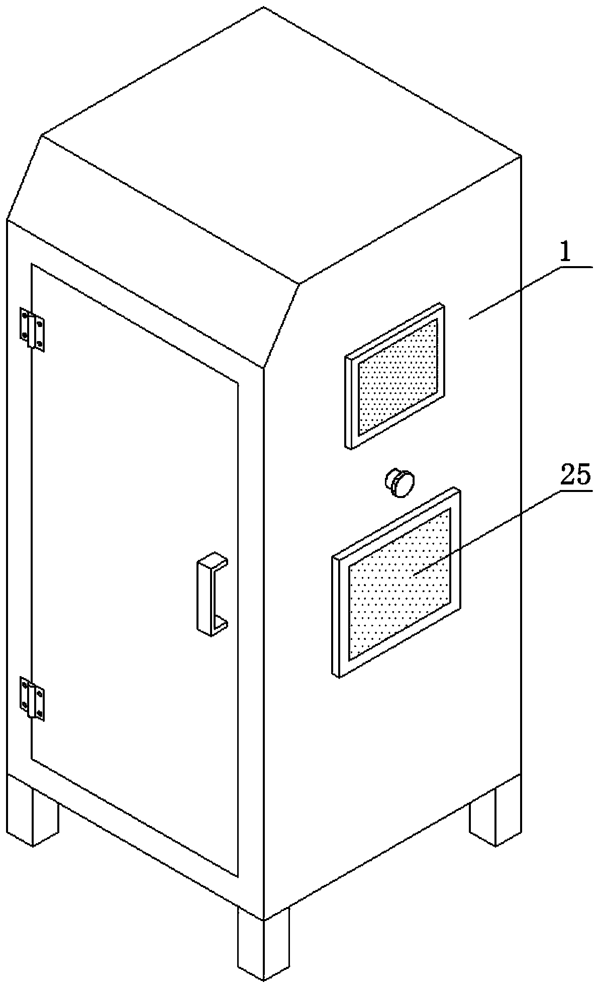
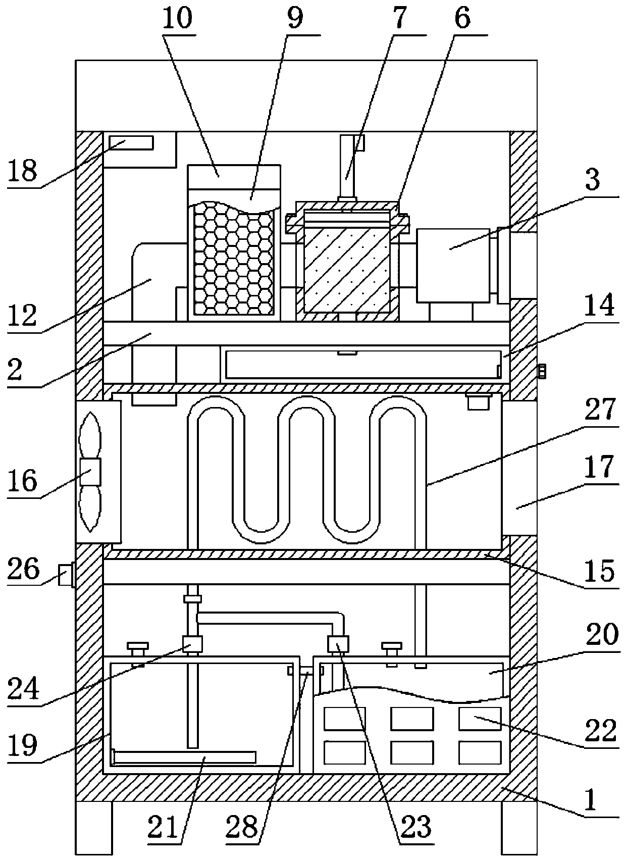
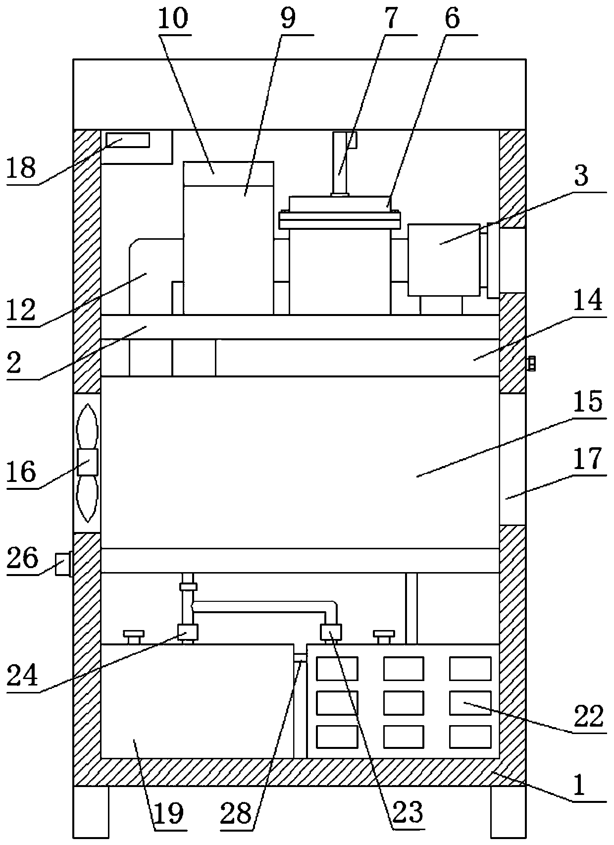
[0021] Example: such as Figure 1-5 As shown, an intelligent constant temperature dehumidification device includes a body 1, a support plate 2 is fixedly installed inside the body 1, a water collection tank 14 is fixedly installed on the bottom of the support plate 2, and a thermostatic chamber 15 is fixedly connected to the bottom of the water collection box 14, supporting The top of the plate 2 is provided with an exhaust fan 3, a first dehumidification mechanism and a second dehumidification mechanism in sequence from right to left. The second dehumidification mechanism is composed of a dehumidification cylinder 9, a cylinder cover 10, a dehumidifier 11 and an air outlet pipe 12. The bottom end of the dehumidification box 4 is fixedly connected with a drain pipe 13, and the bottom end of the drain pipe 13 runs through the support plate 2 and the The water collection tank 14 extends to the inside of the water collection tank 14, one end of the air outlet pipe 12 is fixedly c...


PUM


Abstract

The invention discloses an intelligent constant-temperature dehumidification device. The device comprises a machine body. A supporting plate is fixedly installed inside the machine body. A water collection box is fixedly installed at the bottom of the supporting plate. A constant-temperature chamber is fixedly connected with the bottom of the water collection chamber. An exhaust fan, a first dehumidification mechanism and a second dehumidification mechanism are arranged on the top of the supporting plate from right to left in sequence. The first dehumidification mechanism is composed of a dehumidification box, adsorption sponge, a dehumidification cover, an electric telescopic rod and a push plate. The second dehumidification mechanism is composed of a dehumidification barrel, a barrel cover, desiccant and an air outlet pipe. A drainage pipe communicates with the bottom end of the dehumidification box fixedly. According to the intelligent constant-temperature dehumidification device, air in a station is sucked into the dehumidification barrel through the exhaust fan, moisture in the air is adsorbed by the adsorption sponge preliminary, and then enters the dehumidification barrel after being adsorbed by the adsorption sponge, the air is fed into the desiccant so that more moisture can be adsorbed by the desiccant, then the moisture in the air is removed, and the influence causedby moisture to the equipment in the station is reduced.

Description

technical field [0001] The invention relates to a constant temperature dehumidification device, in particular to an intelligent constant temperature dehumidification device. Background technique [0002] The smart substation adopts advanced, reliable, integrated and environmentally friendly smart equipment, with the basic requirements of digitalization of the whole station information, networked communication platform, and standardized information sharing, and automatically completes basic functions such as information collection, measurement, and control. At the same time, it has the ability to support power grids For substations with advanced functions such as real-time automatic control, intelligent adjustment, online analysis and decision-making, and collaborative interaction, the equipment inside the smart substation is in a live running state, and the requirements for humidity are high, and the indoors of the substation are relatively humid during rainy seasons, which m...

Claims


Application Information

Patent Timeline
Patent Type & Authority Applications(China)
IPC IPC(8): F24F3/14F24F5/00H02B1/56H02B1/28
CPCF24F3/1417F24F5/0003H02B1/56H02B1/28
Inventor 唐宏飞
Owner 徐州瓦特电气科技有限公司
Why Eureka
Try Eureka