Supercharge Your Innovation With Domain-Expert AI Agents!

Slide rheostat

A sliding rheostat and slider technology, applied in sliding contact resistors and other directions, can solve the problems of reduced work efficiency, inconvenient replacement of resistance wires, and wear and tear of resistance wires, so as to improve work efficiency and facilitate disassembly and replacement of resistance wires.

Inactive Publication Date: 2019-03-01
JIANGMEN CITY XINHUI DISTRICT GUJING HENGYI FOOD
View PDF0 Cites 2 Cited by
  • Summary
  • Abstract
  • Description
  • Claims
  • Application Information

AI Technical Summary

Problems solved by technology

[0005] Aiming at the deficiencies of the prior art, the present invention provides a sliding rheostat, which solves the problem that when the current sliding rheostat is used frequently, the sliding piece will cause certain wear and tear on the resistance wire, which makes it inaccurate when people adjust the resistance, thus The data measured by the experiment is inaccurate, so the resistance wire needs to be replaced. However, the slide plate is stuck on the resistance wire, and the slide plate hinders the replacement of the resistance wire. Therefore, it is very inconvenient for people to replace the resistance wire. People need to use tools to remove the slide to replace the resistance wire, which not only wastes people's time and physical strength, but also prolongs the time for replacing the resistance wire, thereby reducing people's work efficiency, and the existing sliding rheostat will appear when it is moving. Shaking, affecting the stability of the sliding rheostat

Method used


Image

  • Slide rheostat
  • Slide rheostat
  • Slide rheostat

Examples


Embodiment Construction

[0021] The following will clearly and completely describe the technical solutions in the embodiments of the present invention with reference to the accompanying drawings in the embodiments of the present invention. Obviously, the described embodiments are only some, not all, embodiments of the present invention. Based on the embodiments of the present invention, all other embodiments obtained by persons of ordinary skill in the art without making creative efforts belong to the protection scope of the present invention.

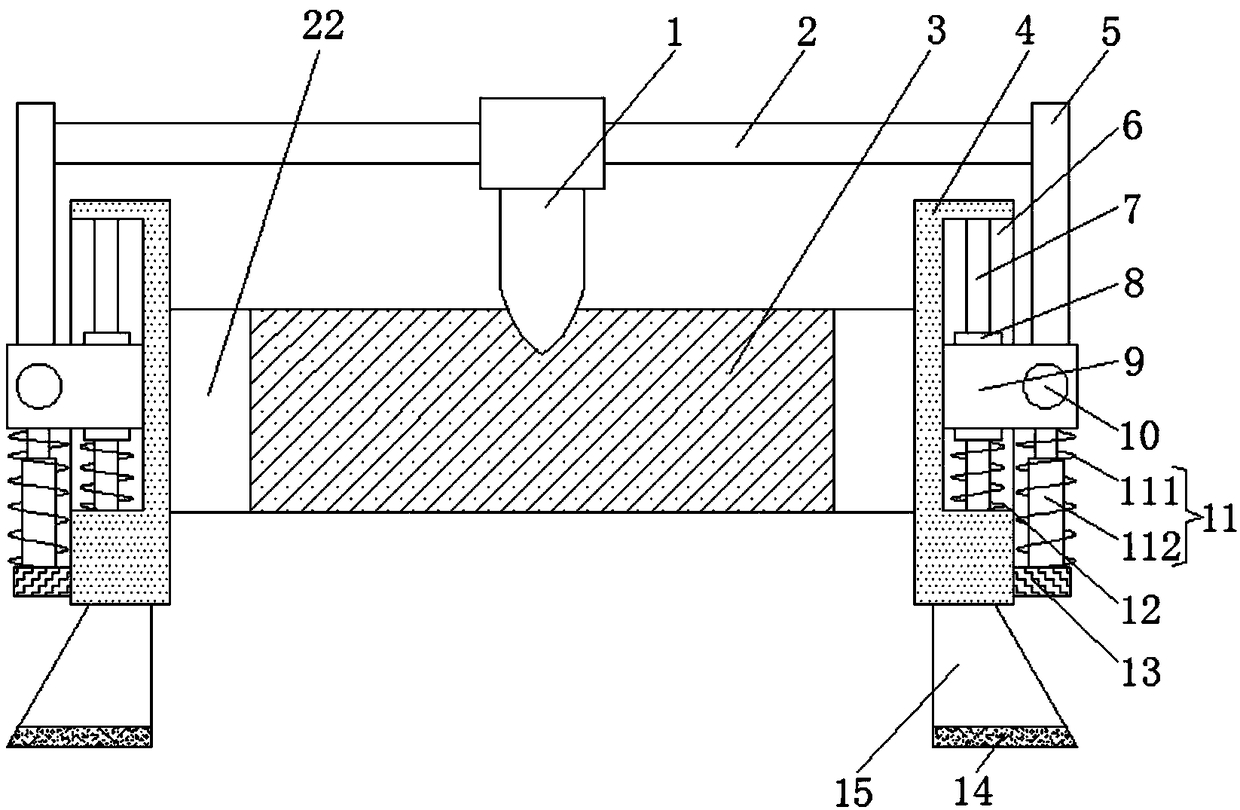
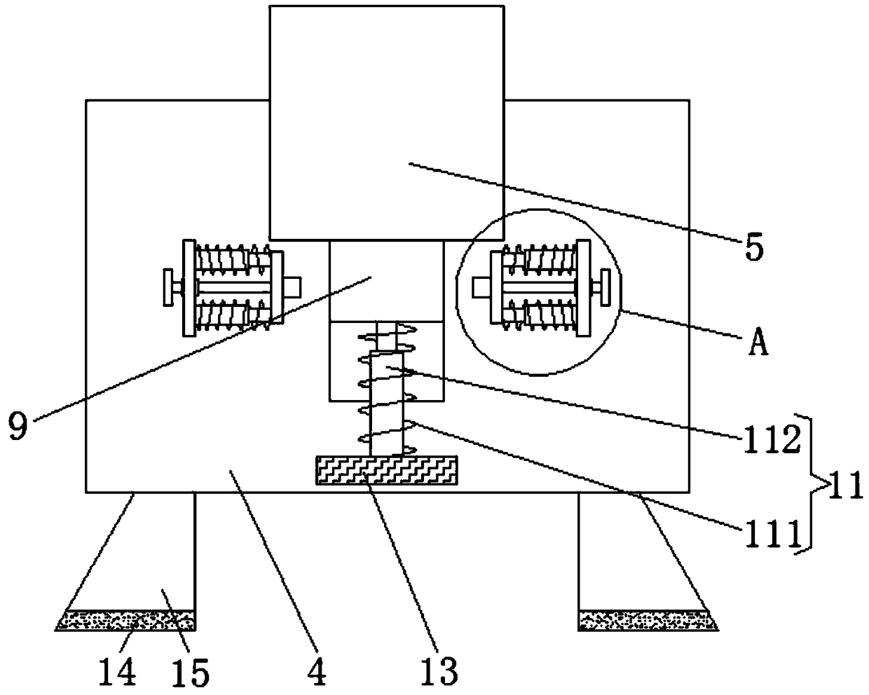
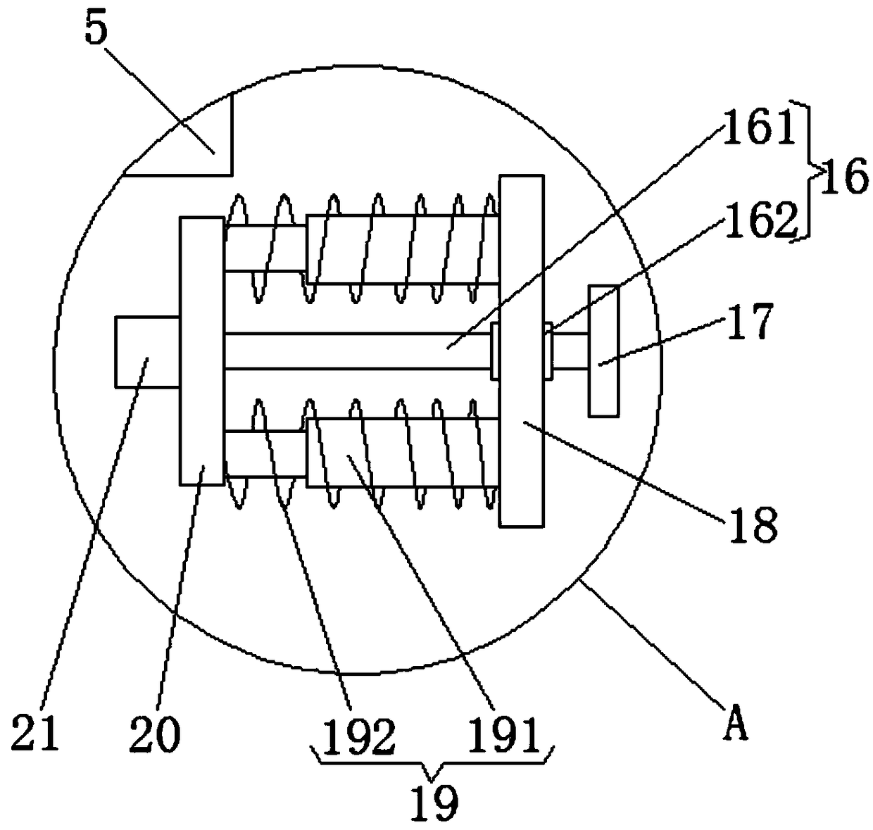
[0022] Such as Figure 1-3As shown, the present invention provides a technical solution: a sliding rheostat, including a porcelain cylinder 22, the left and right sides of the porcelain cylinder 22 are respectively fixedly connected with the opposite surfaces of two partitions 4, and the lower surface of the partition 4 is fixedly connected with Two support legs 15, the lower surface of the support leg 15 is fixedly connected to the upper surface of the anti-s...


PUM


Abstract

The invention discloses a slide rheostat. The slide rheostat comprises a ceramic cylinder, wherein the left side face and the right side face of the ceramic cylinder are fixedly connected with the opposite faces of two separation plates respectively, the outer surface of the ceramic cylinder is wound with a resistance wire, the outer surface of the resistance wire is in lap jointing with the backface of a slide sheet, the slide sheet is arranged on the outer surface of a metal rod, and the left end and the right end of the metal rod are fixedly connected with the opposite faces of two fixingplates. According to the slide rheostat, two pushing plates are enabled to be away from each other by pulling two handles of the separation plate on the left side, thus the two pushing plates drive two clamping blocks to be away from each other, the two clamping blocks are not clamped in a clamping groove any longer, meanwhile, a first telescopic device elongates to drive a sliding block to move upwards, so that the sliding block drives the fixing plates to move upwards, the two fixing plates can move upwards simultaneously to drive the metal rod to move upwards by pulling two handles of the separation plate on the right side, thus the slide sheet is not clamped on the resistance wire any longer, people can conveniently dismount and replace the resistance wire, and accordingly the workingefficiency of people is improved.

Description

technical field [0001] The invention relates to the technical field of variable voltage rheostat devices, in particular to a sliding rheostat. Background technique [0002] Sliding rheostat is a circuit element, which can change its own resistance by changing its resistance, so as to play the role of controlling the circuit. In circuit analysis, sliding rheostat can be used as a fixed value resistor or a variable value resistor. [0003] When the current sliding rheostat is often used, the sliding piece will cause certain wear and tear on the resistance wire, which makes people inaccurate when adjusting the resistance, thus making the experimental measurement data inaccurate, so the resistance wire needs to be replaced, but the sliding rheostat The sliding piece is stuck on the resistance wire, and the sliding piece hinders the replacement of the resistance wire, so it is very inconvenient for people to replace the resistance wire, so people need to use tools to remove the s...

Claims


Application Information

Patent Timeline
Patent Type & Authority Applications(China)
IPC IPC(8): H01C10/38
CPCH01C10/38
Inventor 何颖
Owner JIANGMEN CITY XINHUI DISTRICT GUJING HENGYI FOOD
Features
  • R&D
  • Intellectual Property
  • Life Sciences
  • Materials
  • Tech Scout
  • Unparalleled Data Quality
  • Higher Quality Content
  • 60% Fewer Hallucinations
Learn More