A triangular prism-type deployable planar film antenna mechanism

A technology of triangular prism and unfolding mechanism, which is applied in the direction of folding antennas, etc., can solve the problems of complex driving mechanism, low reliability of unfolding, and increased structural weight

Active Publication Date: 2020-07-07
HARBIN INST OF TECH
View PDF7 Cites 0 Cited by
  • Summary
  • Abstract
  • Description
  • Claims
  • Application Information

AI Technical Summary

Problems solved by technology

[0004] The purpose of the present invention is to solve the problem that the existing articulated support arm has a complicated driving mechanism, greatly increases the structural weight, and has low deployment reliability.
Furthermore, a triangular prism type deployable planar film antenna mechanism is provided

Method used


Image

  • A triangular prism-type deployable planar film antenna mechanism
  • A triangular prism-type deployable planar film antenna mechanism
  • A triangular prism-type deployable planar film antenna mechanism

Examples


specific Embodiment approach 1

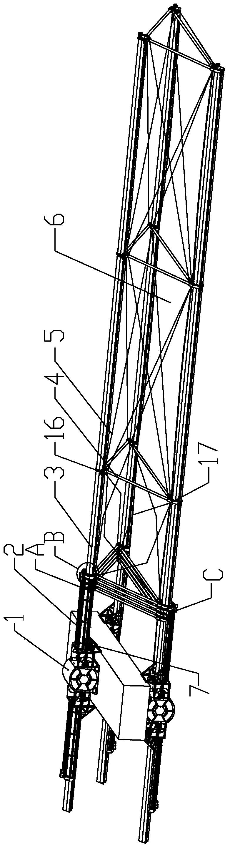
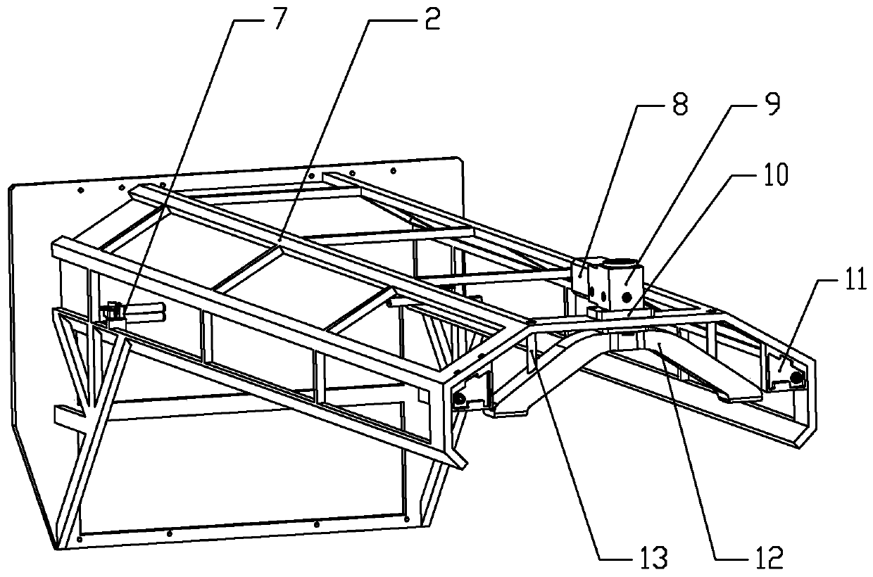
[0023] Specific implementation mode one: combine Figure 1 to Figure 9 Describe this embodiment, a triangular prism-type expandable planar film antenna mechanism of this embodiment, including an elastic extension rod deployment mechanism 1; it also includes two pulley locking mechanisms and multiple pulley mechanisms, and the two pulley locking mechanisms Symmetrically installed on the left and right sides of the elastic stretch rod expansion mechanism 1, each pulley locking mechanism is locked with a plurality of pulley mechanisms, and the multiple pulley mechanisms are formed by the stretching of the three elastic stretch rods 3 of the elastic stretch rod expansion mechanism 1. Prismatic truss unit; each pulley locking mechanism includes a slideway 2, a guide mechanism 7, a motor 8, a right-angle reducer 9, a limit block 11, a spring limit clip 27 and a locking assembly, and one end of the slideway 2 is connected to the elastic The side end faces of the extension rod expansi...

specific Embodiment approach 2

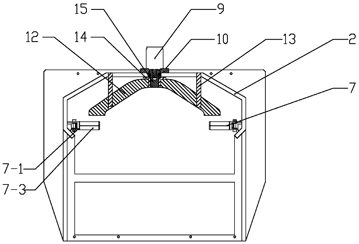
[0029] Specific implementation mode two: combination figure 2 and image 3 Describe this embodiment. The locking assembly of this embodiment includes a concave arc-shaped compression sleeve 12, a threaded sleeve 14 and a threaded column 15. The threaded column 15 is connected to the output end of the right-angle reducer 9. The threaded sleeve 14 is installed on the threaded column. 15, the opening of the concave arc compression sleeve 12 is installed downwards on the threaded sleeve 14. Such setting facilitates the rotation of the threaded column 15 under the control of the right-angle reducer 9, and the threaded column 15 drives the threaded sleeve 14 and the concave arc-shaped compression sleeve 12 to move up and down, thereby realizing the locking and releasing of the pulley mechanism The action and operation are simple and flexible, and other components and connections are the same as those in the first embodiment.

[0030] In the action of the pulley mechanism in this em...

specific Embodiment approach 3

[0031] Specific implementation mode three: combination figure 2 and image 3 To illustrate this embodiment, the locking assembly of this embodiment further includes a guide strut 13 installed on the concave arc-shaped compression sleeve 12 , and the guide strut 13 slides through the slideway 2 . Such setting is convenient for ensuring precise locking and preventing errors during the locking process. Other compositions and connections are the same as those in Embodiment 1 or 2.


PUM


Abstract

The invention discloses a triangular prism shaped extensible plane film antenna mechanism, relates to an antenna mechanism and aims to solve the problems of an existing hinged supporting arm that a driving mechanism is complex, structure weight is greatly increased and expansion reliability is low. Two pulley locking mechanisms are symmetrically installed on the left side and the right side of anelastic extension rod expansion mechanism (1), a plurality of pulley mechanisms are locked on each pulley locking mechanism, and the plurality of pulley mechanisms form a triangular prism truss unit through the extension of three elastic extension rods (3) of the elastic extension rod expansion mechanism (1). The expansion process of the mechanism is realized through the outward extension of the elastic rod, the elastic extension rod is expanded to be under a straight line bulging state which is a stable stage, the elastic extension rod is bent and deformed by a large moment, so that the mechanism does not need a locking device after being expanded, and the mechanism is simple in implementation ways and is stable and reliable in working. The mechanism can be used for fields of aerospace and the defense-related science and technology.

Description

technical field [0001] The invention relates to an antenna mechanism, in particular to a triangular prism type expandable planar film antenna mechanism, which belongs to the field of aerospace and national defense science and technology. Background technique [0002] With the rapid development of space communication, earth observation, deep space exploration, and manned spaceflight, the demand for large-scale, lightweight, and high-geometric stability aerospace space agencies has become very urgent, but limited by the volume of the rocket fairing Due to the limitation of space travel, it is necessary to design a space-expandable mechanism with a large expansion ratio, which is in a folded state during the transportation and launch stages, and unfolds into a working state after the spacecraft enters orbit. The design and related research of the space folding mechanism is one of the key fundamental issues in the development of the future aerospace industry. [0003] In all ki...

Claims


Application Information

Patent Timeline
Patent Type & Authority Patents(China)
IPC IPC(8): H01Q1/08
CPCH01Q1/08
Inventor 郭宏伟杨皓宇李冰岩邓宗全刘荣强
Owner HARBIN INST OF TECH
Why Eureka
Try Eureka