

Electrical equipment box door convenient to open and close and electrical equipment box with cabinet door
A technology for electrical equipment boxes and electrical equipment, applied in electrical equipment shells/cabinets/drawers, electrical components, chassis/boxes/drawer parts and other directions, can solve problems such as inconvenient door opening and closing, and ensure structural stability. safety and performance, avoiding gaps, avoiding water leakage
- Summary
- Abstract
- Description
- Claims
- Application Information
AI Technical Summary
Problems solved by technology
Method used
Image

Examples
Embodiment 1
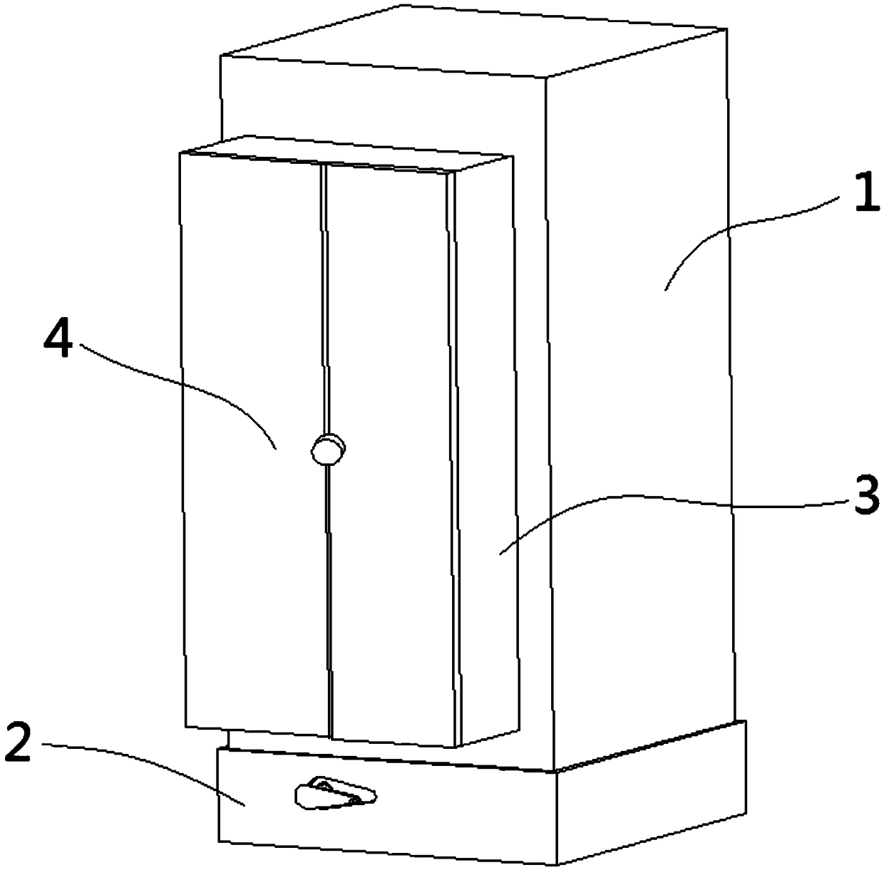
[0040] Electrical equipment box doors that are easy to switch and electrical equipment boxes with such doors, such as figure 1 As shown, it includes a box body 1 with a built-in cavity in the shape of a cuboid, a bracket 11 is placed in the cavity of the box body 1, and required components are installed on the bracket 11 .
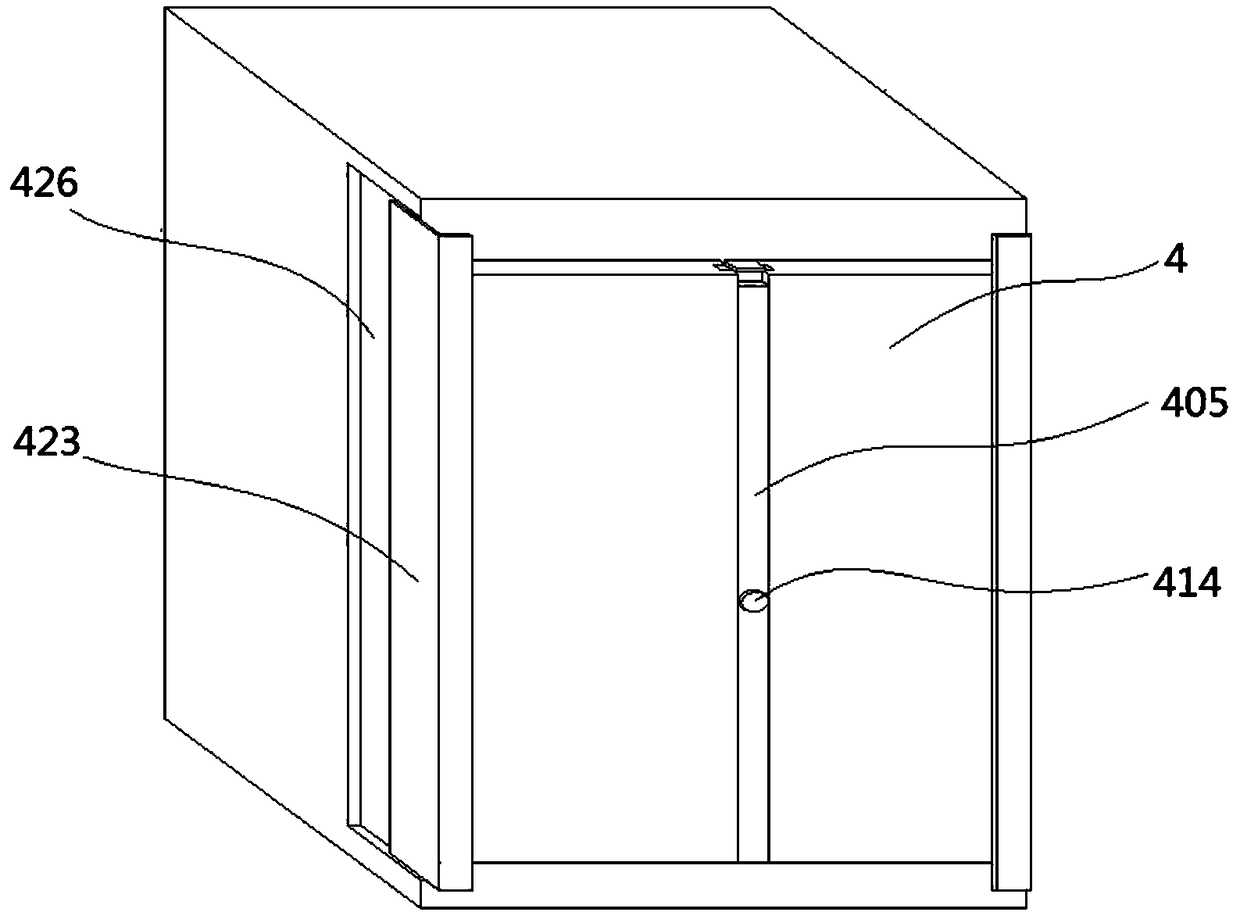
[0041] The bottom of the box body 1 is provided with a base 2, the box body 1 is fixed on the base 2, and the box body 1 is provided with a volume expansion body 3 that can protrude from the front end of the box body 1 and perform linear reciprocating motion along the width direction of the box body 1. The extension body 3 is a rectangular frame body including four side panels and a door body 4 is provided on the front end. The cavity of body 1 forms a cavity. After opening the door body 4, the components in the box body 1 and the volume expansion body 3 can be observed, and then the internal components can be installed, repaired, replaced and other operat...
Embodiment 2
[0065] The electrical equipment box door that is convenient to switch and the electrical equipment box with the cabinet door include a box body 1 with a built-in cavity and a cuboid shape, a bracket 11 is placed in the cavity of the box body 1, and required components are installed on the bracket 11 .
[0066] The bottom of the box body 1 is provided with a base 2, the box body 1 is fixed on the base 2, and the front end of the box body 1 is provided with a door. After opening the door, the components in the box body 1 can be observed, and then the internal components can be checked. Installation, maintenance, replacement and other operations.
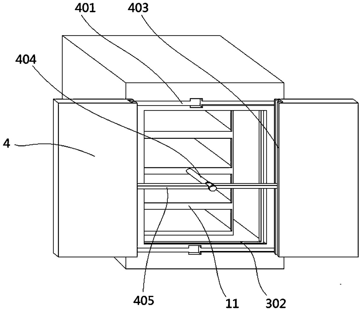
[0067] The base 2 is a rectangular frame structure with a bottom plate 201, and the bottom surface of the box body 1 constitutes the top plate 224 of the base 2, such as Figure 2-9 As shown, in this embodiment, a bracket 11 for placing components is fixed inside the box body 1. The door includes two left and right door bodies 4 on the...
PUM
 Abstract
Description
Claims
Application Information