Stapler power handle

A stapler and power technology, applied in the field of medical devices, can solve the problems of increased use cost, difficult to dissipate heat, inconvenient to operate, etc., and achieve the effects of easy installation and heat dissipation, avoiding scattering or messy, and facilitating overall arrangement

Pending Publication Date: 2019-03-05
CHONGQING XISHAN SCI & TECH
View PDF0 Cites 2 Cited by
  • Summary
  • Abstract
  • Description
  • Claims
  • Application Information

AI Technical Summary

Problems solved by technology

Although the problems of laborious operation and high cost of use have been overcome, there are still defects:
[0005] 1. The multiple motors used to drive the stapler for cutting, stapling, bending and rotating are all arranged on the upper part of the housing. The structural arrangement is complex and the transmission mechanisms are numerous, which increases the volume of the upper part of the housing and makes the entire power handle heavy.
[0006] 2. Multiple motors are clustered on the upper part of the casing, which generates a lot of heat, and it is not easy to dissipate heat in the closed casing, which affects the normal operation of other components such as electronic components
[0007] 3. The battery is installed at the lower end of the grip part of the handle of the shell. When holding it, the lower end feels heavy, unbalanced front and rear, and inconvenient to operate.
[0008] 4. The process of cleaning, disinfection and sterilization after use is complicated, and the handle as a whole cannot be sterilized by high-temperature cooking
The handle shell is a one-time use detachable structure. Every time it is used, the shell needs to be sterilized and sterilized separately, and then the shell is installed on the handle for surgery. After the operation, the used shell will be scrapped. Replacing a new sterilized shell during use, on the one hand, it is troublesome to install and disassemble, and on the other hand, the disposable shell increases the cost of use; in addition, the handle structure as a whole cannot be sterilized at high temperature, and there is a risk of infection caused by insufficient sterilization

Method used


Image

  • Stapler power handle
  • Stapler power handle
  • Stapler power handle

Examples


Embodiment 1

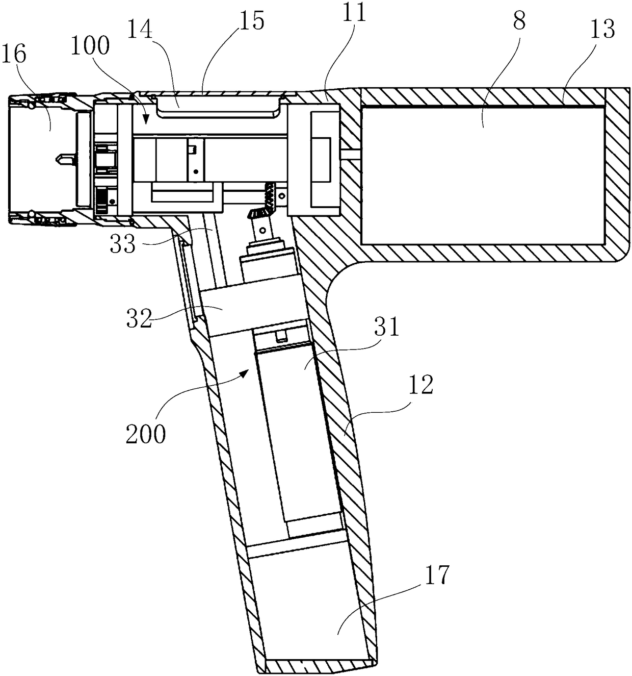
[0079] Such as Figure 1 to Figure 4 As shown, a stapler power handle includes a shell, a power mechanism, and a battery 8. The shell is composed of a shell body 11 and a handle 12. The shell body 11 is arranged horizontally, and the handle 12 is connected below the shell body 11. , the power mechanism includes a first power unit 2 and a second power unit 3, the first power unit is arranged laterally in the middle front of the housing 11, the second power unit is arranged in the handle 12, and the rear of the housing 11 is provided with a battery Compartment 13, the battery 8 is arranged in the battery compartment 13. The power mechanism is dispersedly arranged in the handle 12 and the shell body 11, making full use of the space of the handle 12, simplifying the structure to avoid crowding, and facilitating the installation and heat dissipation of each power unit; and the battery 8 is arranged at the rear of the shell body 11 to play a role Fore and aft balance. Compared wit...

Embodiment 2

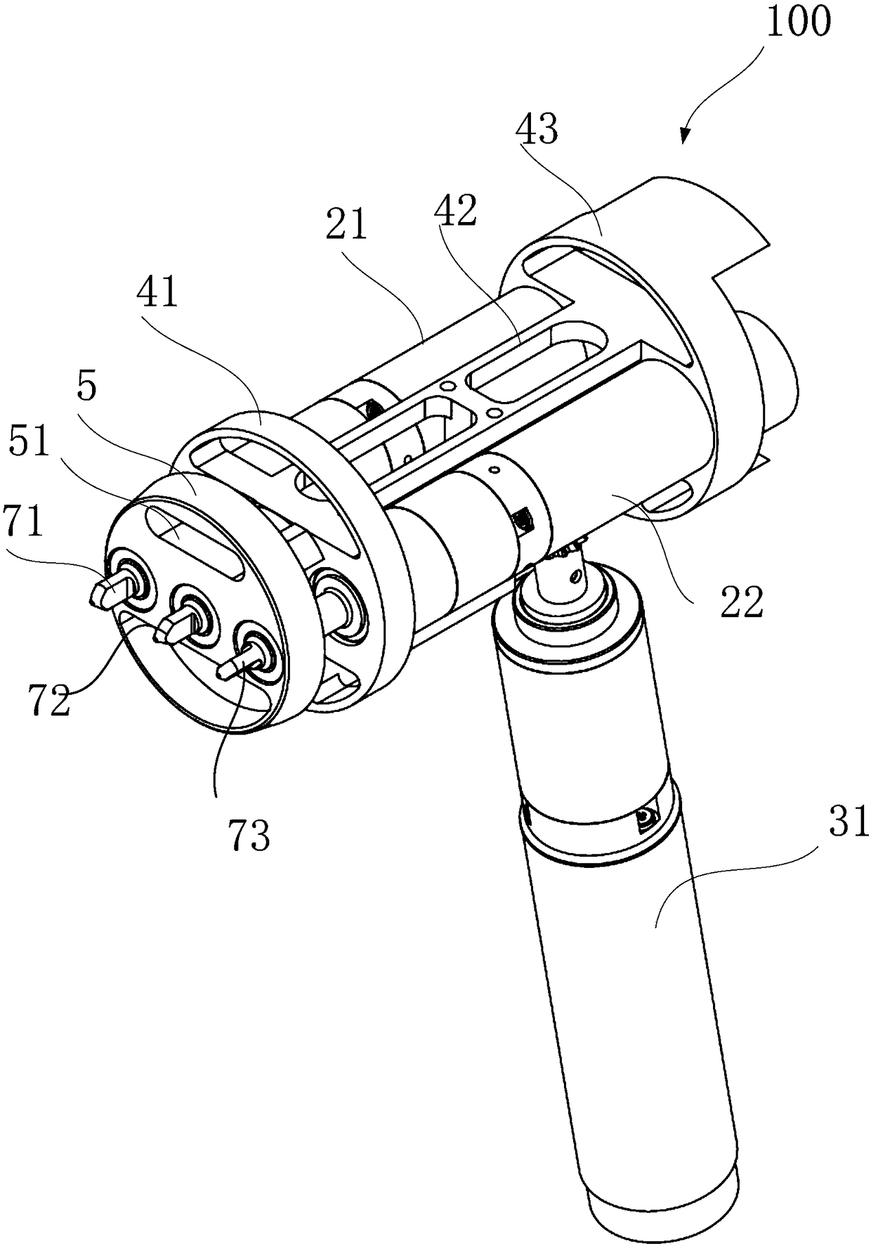
[0105] Such as Figure 7 and figure 2As shown, a power structure of a stapler power handle includes a housing, a plurality of motors and a power head corresponding to the motors, wherein the housing is composed of a housing body 11 and a handle 12, the housing body 11 is arranged horizontally, and the handle 12 Connected under the shell body 11, at least one motor is arranged in the handle, and at least two motors are arranged in the shell body parallel to each other. The motors are dispersedly arranged in the handle 12 and the housing body 11 to make full use of the space of the handle 12, simplify the structure to avoid clustering, and facilitate the installation and heat dissipation of each power unit. Compared with the prior art, the structural arrangement and space utilization are more reasonable.

[0106] Wherein, a first motor 21 and a second motor 22 are arranged in the shell body 11 , and a third motor 31 is arranged in the handle 12 . The first motor 21 and the se...

Embodiment 3

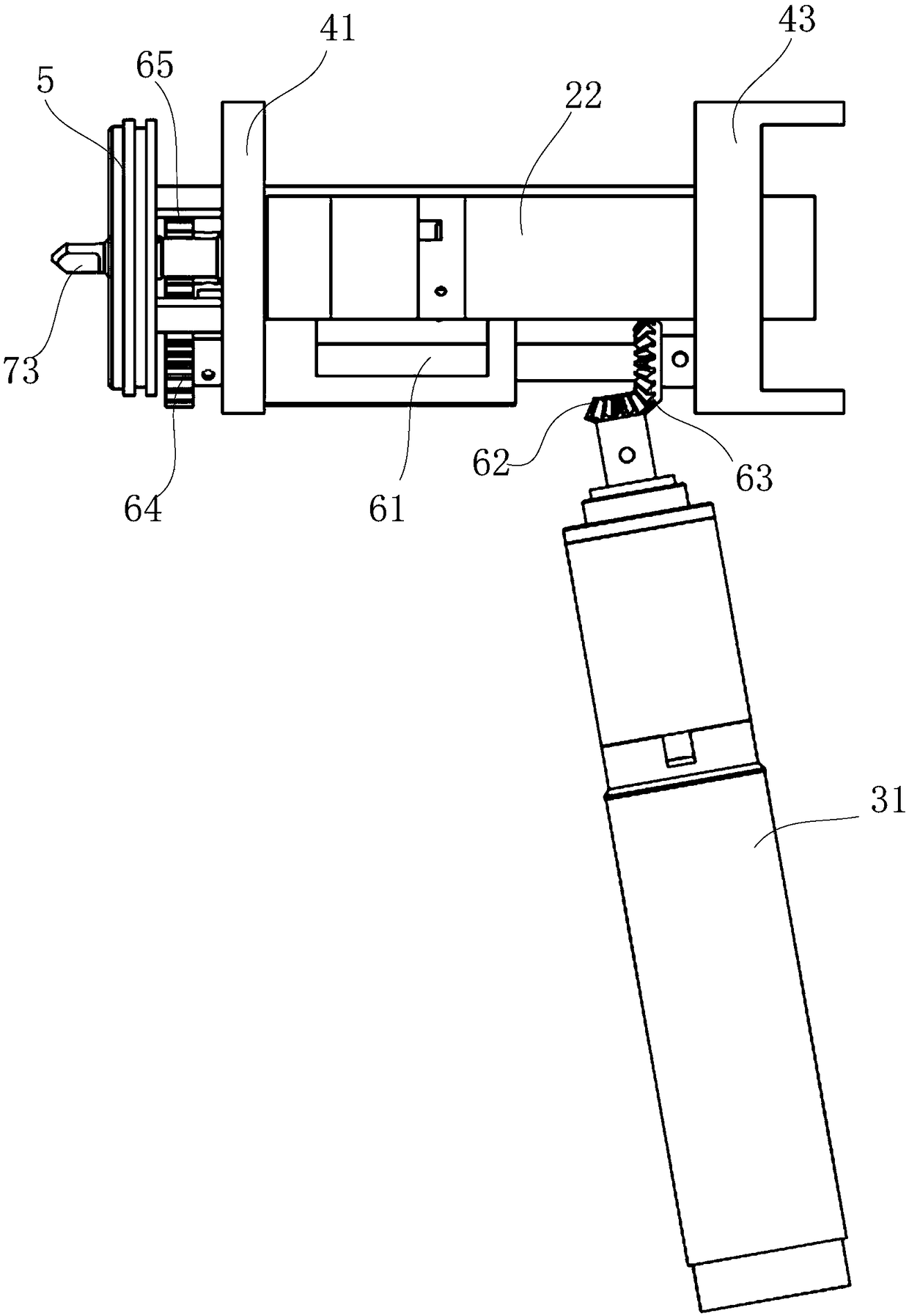
[0111] Such as Figure 8 to Figure 6 As shown, on the basis of Embodiment 1, in order to facilitate the installation of the first motor 21, the second motor 22, the transmission mechanism and the power head 71, 72, 73, a support mechanism is also provided, the first motor 21 and the second motor 22 Be installed on the support mechanism, power head 71,72,73 is installed on the support mechanism front.

[0112] Among them, the power heads 71, 72, 73, the first motor 21, the second motor 22 and the main part of the transmission mechanism integrated on the support mechanism form a module; the method of first integrating into a modular structure and then assembling ensures that each The orderly installation of components prevents them from being scattered or messy after being installed in the housing, and facilitates the overall layout of the device structure.

[0113] Such as Figure 6 As shown, the power head includes a power shaft 701 and a flat head 702 located at the front e...


PUM


Abstract

The invention provides a stapler power handle. The power handle comprises a housing, a power mechanism and a battery. The housing comprises a housing body and a handle connected with the housing body,the power mechanism comprises a first power unit and a second power unit, the first power unit is arranged in the front middle part of the housing body, the second power unit is arranged in the handle, and the battery is arranged at the inner rear part of the housing. According to the stapler power handle, the power mechanism is arranged in the handle and the housing body respectively, handle space is fully utilized, the structure is simplified to prevent gathering, the installing and heat dissipating of the power units are facilitated, the battery is arranged in the tail part of the housingbody, and the purpose of front and back balancing is achieved.

Description

technical field [0001] The invention belongs to the technical field of medical instruments, and in particular relates to a power handle of a stapler. Background technique [0002] At present, laparoscopic cutting staplers are mainly divided into three types: disposable manual laparoscopic cutting staplers, disposable electric laparoscopic cutting staplers, and electric cutting staplers. [0003] Among them, the disposable manual laparoscopic cutting stapler has the problems of laborious operation, unstable anastomotic cutting, poor forming consistency of titanium nails and high cost of use. For the disposable electric laparoscopic cutting stapler, the same handle can only replace the staple cartridge of the same length model, which is not universal; the handle is scrapped after using the manual emergency retraction function, and the one-time use cost is high. [0004] In view of the above shortcomings, an electric cutting stapler has been developed. Its power handle is main...

Claims


Application Information

Patent Timeline
IPC IPC(8): A61B17/115
CPCA61B17/1155A61B2017/00982A61B2017/00367
Inventor 郭毅军吴治中黄勇钟定恩张兴伟曾健
Owner CHONGQING XISHAN SCI & TECH
Why Eureka
Try Eureka