Engine components with crankcase oil-air separation system

A separation system and engine technology, applied to engine components, crankcase ventilation, machine/engine, etc., can solve problems such as mechanical structure limitations, affecting the filtering effect of oil and gas separators, and achieve the effect of improving design flexibility

Active Publication Date: 2020-10-16
SAIC MOTOR
View PDF8 Cites 0 Cited by
  • Summary
  • Abstract
  • Description
  • Claims
  • Application Information

AI Technical Summary

Problems solved by technology

However, limited by the specific mechanical structure of the engine, the inlet of the oil-air separator designed in this way is often located above the moving parts in the engine such as the crankshaft
In this way, when the engine is running, due to the rotation of the crankshaft, the engine oil will occasionally be thrown to the above-mentioned inlet, which will affect the filtering effect of the oil-gas separator instead.

Method used


Image

  • Engine components with crankcase oil-air separation system
  • Engine components with crankcase oil-air separation system
  • Engine components with crankcase oil-air separation system

Examples


Embodiment Construction

[0026] In the various figures of the present invention, structurally identical or functionally similar features are indicated by the same reference numerals.

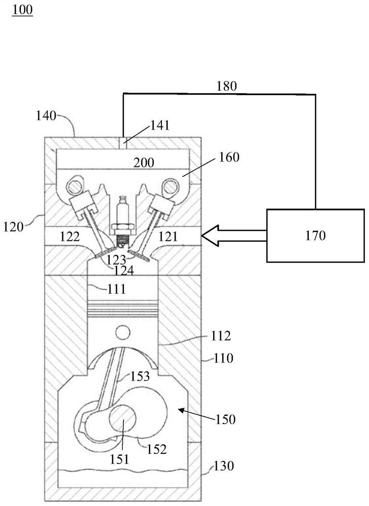
[0027] figure 1 An engine assembly 100 according to one embodiment of the invention is schematically shown. In the context of the present invention, the engine may be a combustion engine such as an internal combustion engine. In addition, it should be noted that the engine can be a multi-cylinder engine, while figure 1 A sectional view of only one cylinder structure in the engine is shown.

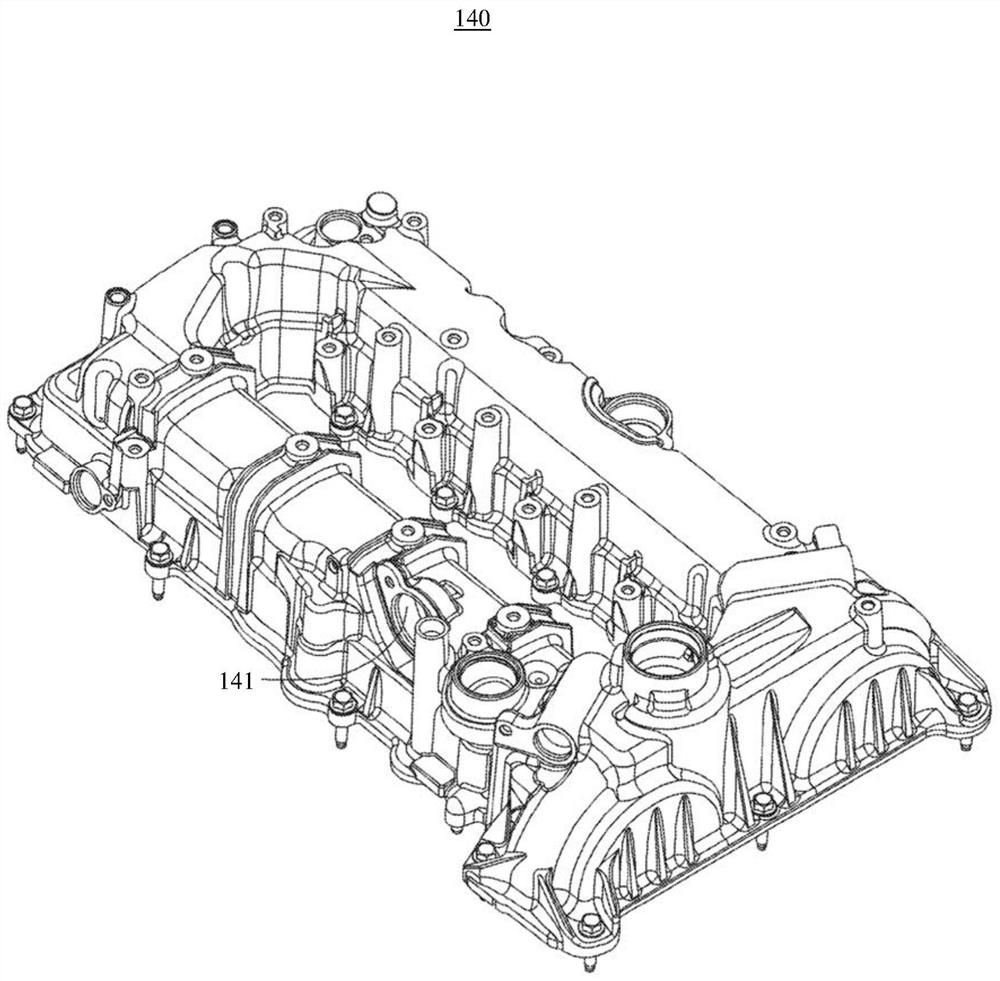
[0028] like figure 1 As shown, the engine assembly 100 includes a cylinder block 110 , a cylinder head 120 airtightly connected to the cylinder block 120 , an oil pan 130 airtightly connected to the cylinder block 110 , and a cylinder head airtightly connected to the cylinder head 120 Cover 140 . A cylinder 111 is defined within the cylinder block 110 . A piston 112 is attached to the air cylinder 111 so as to be able to move ...


PUM


Abstract

The invention provides an engine assembly. The engine assembly comprises a cylinder cover, a cylinder cover shell and an oil-gas separation system, wherein the cylinder cover and the cylinder cover shell are in gas tightness connection so that an inner space can be defined, and the inner space communicates with a crank case of the engine assembly; the oil-gas separation system comprises a partition plate installed on the cylinder cover shell, a gas channel independent of the inner space is defined between the partition plate and the cylinder cover shell, and a filtering path of the oil-gas separation system is limited by the gas channel; the oil-gas separation system is provided with an inlet and communicates with fluid in the inner space so that blow-by gas coming from the crank case is supplied into the oil-gas separation system from the inner space through the inlet, in addition, the oil-gas separation system is further provided with a plurality of filtering baffles, and the filtering baffles are arranged in the gas channel so as to filter the supplied blow-by gas along the filtering path; and the oil-gas separation system comprises a guiding channel formed between the inlet andthe gas channel, and thus, the supplied blow-by gas can flow in the guiding channel and the gas channel without influencing each other.

Description

technical field [0001] The present invention generally relates to engine assemblies having crankcase oil-air separation systems. Background technique [0002] During the working process of an engine such as an internal combustion engine, the mixed gas in the cylinder may escape into the crankcase through the gap between the piston and the inner wall of the cylinder, which is called "blow-by gas". The blow-by gas contains fuel component particles, so if it is mixed with the engine oil in the crankcase, it will deteriorate the quality of the engine oil. In addition, according to legal requirements, this blow-by gas cannot be directly discharged to the outside world, so it is usually returned to the intake system of the engine and re-enters the cylinder to burn and do work. However, when the engine is running, the engine oil in the crankcase will be in a high-pressure gas state. If the blow-by gas mixed with oil droplets directly enters the cylinder for combustion, it will cau...

Claims


Application Information

Patent Timeline
Patent Type & Authority Patents(China)
IPC IPC(8): F01M13/04F02F7/00
CPCF01M13/04F01M2013/0438F02F7/0065
Inventor 乔治·豪顿
Owner SAIC MOTOR
Why Eureka
Try Eureka