combustion engine system

A combustion engine, internal combustion engine technology, applied in the direction of combustion engine, internal combustion piston engine, engine components, etc.

Active Publication Date: 2020-03-24
MAN ENERGY SOLUTIONS FILIAL AF MAN ENERGY SOLUTIONS SE TYSKLAND
View PDF5 Cites 0 Cited by
  • Summary
  • Abstract
  • Description
  • Claims
  • Application Information

AI Technical Summary

Problems solved by technology

[0004] Therefore, an object of the present invention is to completely or partially overcome the above-mentioned disadvantages and disadvantages of the prior art

Method used


Image

  • combustion engine system
  • combustion engine system
  • combustion engine system

Examples


Embodiment Construction

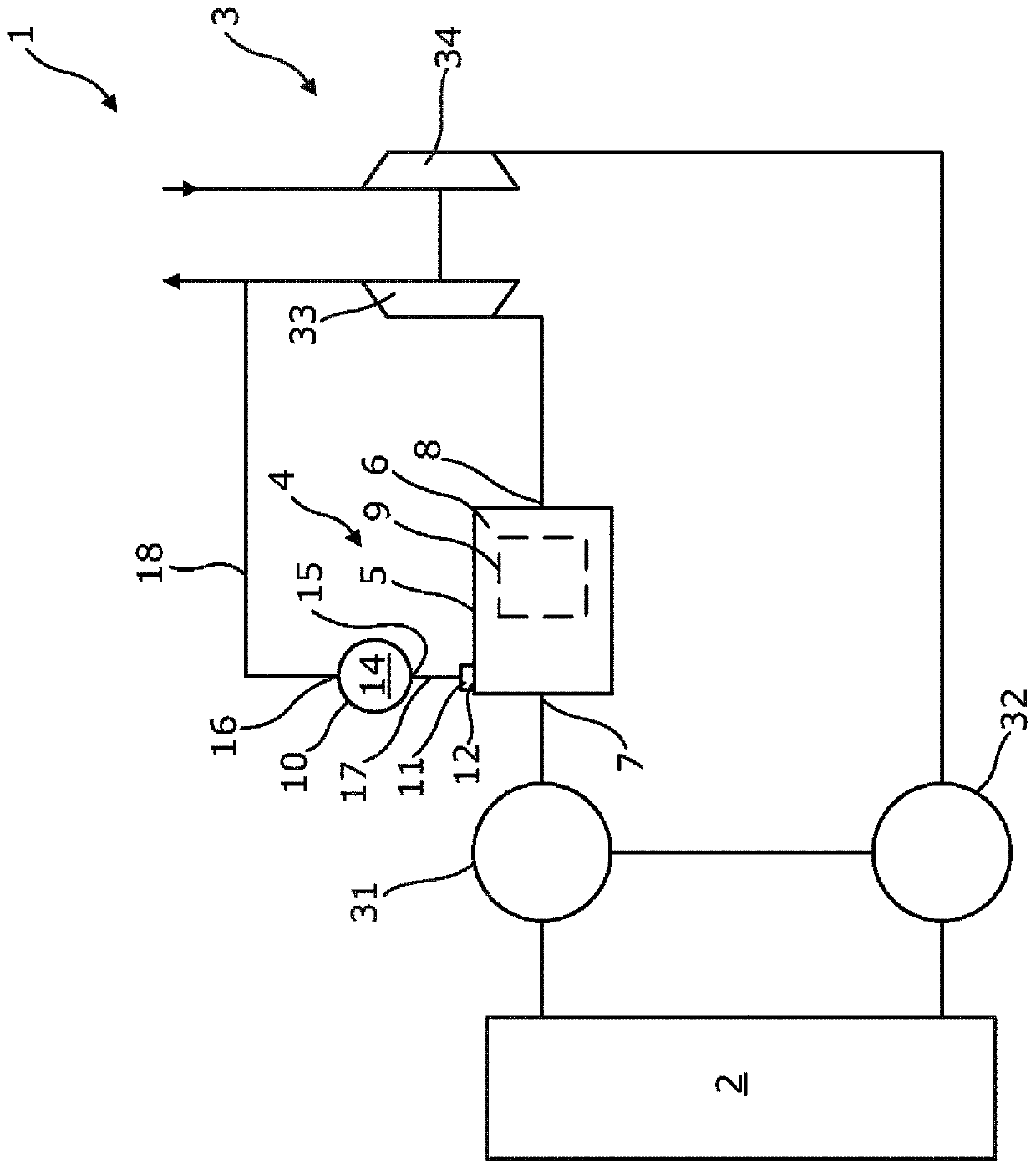
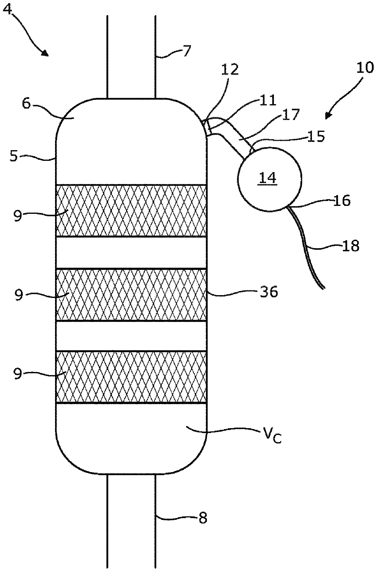
[0059] figure 1 A combustion engine system 1 is shown which includes an internal combustion engine 2 producing exhaust gas. The combustion engine system 1 comprises a turbocharger 3 , which is driven by exhaust gases from the high-pressure side of the turbocharger 3 . The combustion engine system 1 also includes a NO x A reduction unit 4, which is in fluid communication with the internal combustion engine 2, to purify the exhaust gas from the internal combustion engine 2 by selective catalytic reduction (SCR). NO x The reduction unit 4 comprises a catalytic reactor housing 5 with a chamber 6, an inlet pipe 7, an outlet pipe 8 and one or more catalytic elements 9 arranged in a catalytic converter between the inlet pipe 7 and the outlet pipe 8. In the chamber 6 of the reactor shell 5 . in NO xIn the reduction unit 4 , soot deposits on the catalytic elements 9 and on all surfaces within the catalytic reactor housing 5 during exhaust gas purification. Therefore, the combusti...


PUM


Abstract

The invention relates to a combustion engine system comprising an internal combustion engine producing exhaust gas containing soot, a turbocharger and NO x reduction unit, the soot deposits on the NO x reduction unit, the NO x The reduction unit includes a catalytic reactor housing having a chamber, an inlet pipe and an outlet pipe, and one or more catalytic elements, and the combustion engine system further includes a soot removal unit including a valve in fluid communication with an opening of the catalytic reactor housing, A receiver having a receiver cross-sectional area and a receiver inlet and an exhaust port, the valve having an open position to allow at least a portion of the exhaust gas in the catalytic reactor housing to escape into the soot removal unit, the conduit enabling the receiver inlet is fluidly connected to the valve and has a conduit cross-sectional area smaller than the cross-sectional area of ​​the receiver. The invention also relates to a method for reducing NO in a combustion engine system according to the invention x A soot reduction method for soot in a chamber of a reduction unit.

Description

technical field [0001] The invention relates to a combustion engine system and a method for reducing NO in a combustion engine system according to the invention x A soot reduction method for soot in a chamber of a reduction unit. Background technique [0002] Exhaust gases from internal combustion engines are cleaned to reduce NO in catalytic reactors x emission. During the cleaning process, soot is deposited in the reactor housing and on the surfaces of the catalytic elements in the SCR reactor. To remove soot from the surface, high-pressure air is injected at predetermined intervals to loosen the soot, and the gas carries the loosened soot out of the reactor shell. However, high pressure air is not very effective at loosening the soot and requires extensive equipment, namely high pressure pipes and nozzles, which are expensive and can be difficult to repair or replace. [0003] WO 2006 / 091136 discloses a device for removing particulates from a gas stream which is appli...

Claims


Application Information

Patent Timeline
Patent Type & Authority Patents(China)
IPC IPC(8): F01N3/28F01N3/035F01N3/20F01N3/023
CPCF01N3/023F01N3/035F01N3/206F01N3/28B01D53/86Y02T10/12F01N1/163F01N1/24F01N2340/06F01N2570/14
Inventor S·迈尔
Owner MAN ENERGY SOLUTIONS FILIAL AF MAN ENERGY SOLUTIONS SE TYSKLAND
Why Eureka
Try Eureka