
Oil temperature heating belt control method and air conditioner

A control method and heating belt technology, applied in the direction of machines/engines, pumping device components for elastic fluid, rotary piston type/oscillating piston type pump components, etc., can solve the problem of reduced service life of oil temperature heating belts, Liquid compressor and lubricating oil dilution, oil temperature heating belt failure and other problems, to achieve the effect of reducing standby power, improving energy saving and prolonging service life

Active Publication Date: 2019-03-05
NINGBO AUX ELECTRIC
View PDF5 Cites 5 Cited by
  • Summary
  • Abstract
  • Description
  • Claims
  • Application Information

AI Technical Summary

Problems solved by technology

[0006] 1. Immediately after the compressor is turned off and for a long period of time afterwards, when the temperature of the compressor is higher than the outdoor ambient temperature by a certain temperature, the liquid refrigerant will not accumulate at the bottom of the compressor. Turning on the oil temperature heating belt at this time will cause energy waste;
[0007] 2. When the outdoor temperature is higher than the indoor temperature, the liquid refrigerant will accumulate in the indoor unit instead of the bottom of the compressor, and the oil temperature heating belt will be turned on at this time, resulting in energy waste;
[0008] 3. When the compressor is heated by the oil temperature heating belt to a certain temperature higher than the outdoor ambient temperature, the liquid refrigerant will not accumulate at the bottom of the compressor. At this time, turning on the oil temperature heating belt will cause energy waste;
[0009] 4. The service life of the oil temperature heating belt is greatly reduced. After 2 to 3 years of use of the air conditioner, the oil temperature heating belt may fail, causing the compressor to stop for a long time and then start it again, and the liquid compressor and lubricating oil will be diluted. leading to premature compressor damage

Method used


Image

  • Oil temperature heating belt control method and air conditioner
  • Oil temperature heating belt control method and air conditioner

Examples


Embodiment Construction

[0035] The following will clearly and completely describe the technical solutions in the embodiments of the present invention with reference to the accompanying drawings in the embodiments of the present invention. Obviously, the described embodiments are only some, not all, embodiments of the present invention. Based on the embodiments of the present invention, all other embodiments obtained by persons of ordinary skill in the art without making creative efforts belong to the protection scope of the present invention.

[0036] The oil temperature heating belt control method, control device and air conditioner according to the embodiments of the present invention will be described below with reference to the accompanying drawings.

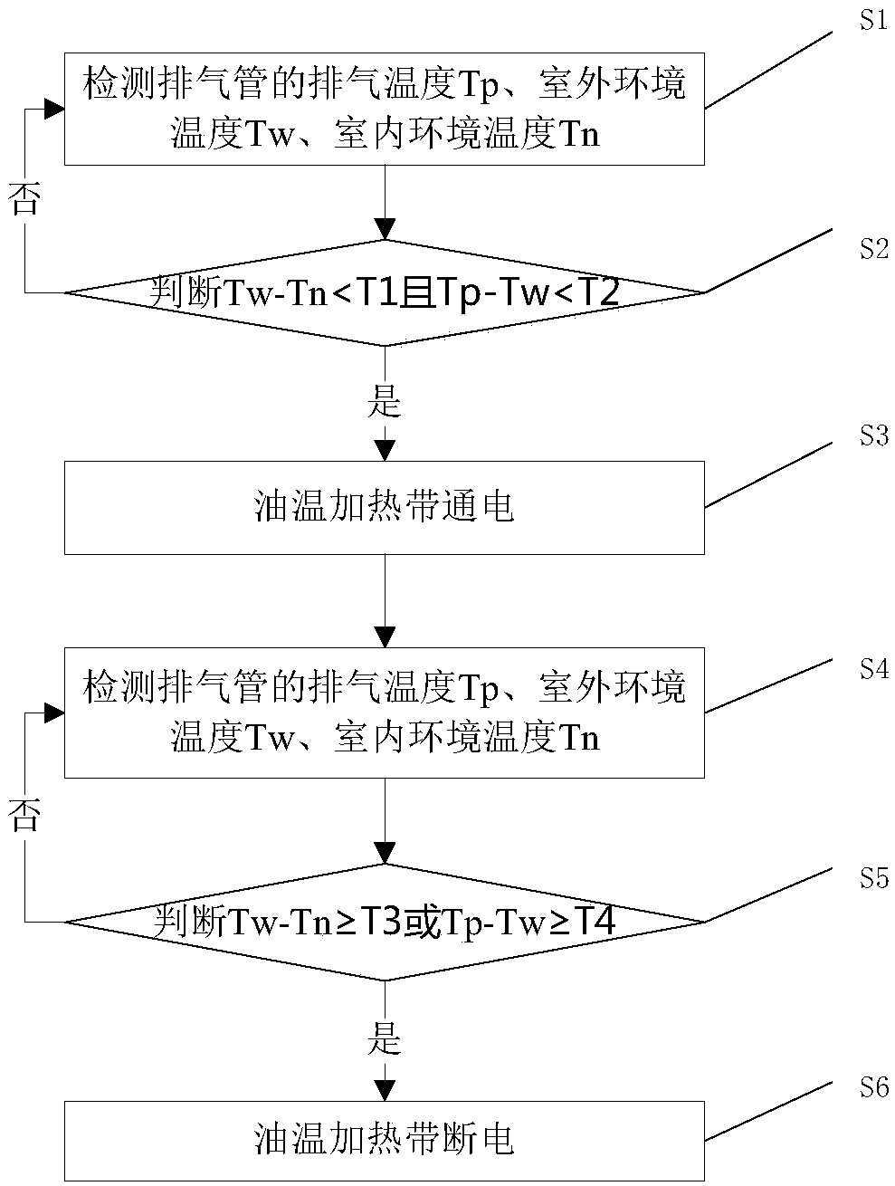
[0037] figure 1 It is a flow chart of the oil temperature heating belt control method of the present invention; as figure 1 As shown, the oil temperature heating band control method includes the following steps:

[0038] S1: Detect the exhaust te...


PUM


Abstract

The invention discloses an oil temperature heating belt control method and device. The control method comprises the following steps that the exhaust temperature Tp, outdoor ambient temperature Tw andindoor ambient temperature Tn of an exhaust pipe are detected; whether the difference between Tw and Tn is less than the preset temperature T1 or not is judged, and whether the difference between Tp and Tw is less than the preset temperature T2 or not is judged; when Tw-Tn is smaller than Ti and Tp-Tw is smaller than T2, an oil temperature heating belt is controlled to be energized; when the oil temperature heating belt is energized, Tp, Tw and Tn are detected continuously; whether Tw-Tn is larger than or equal to T3 or not or Tp-Tw is larger than or equal to T4 or not is judged; and when Tw-Tn is larger than or equal to T3 or Tp-Tw is larger than or equal to T4, the oil temperature control heating belt is controlled to be powered off, and a regulation process is completed. By means of thecontrol method, on-demand starting is realized, unnecessary power consumption of the air conditioner is reduced, standby power of the air conditioner is reduced, energy conservation is improved, andthe service life of the oil temperature heating belt is prolonged.

Description

technical field [0001] The invention relates to the technical field of air conditioners, in particular to an oil temperature heating belt control method and an air conditioner. Background technique [0002] In the air conditioner of the prior art, when the compressor stops running for a long time, a large amount of refrigerant may accumulate at the bottom of the compressor. When the compressor is started, the compressor will absorb a large amount of liquid refrigerant to generate liquid compression. At the bottom of the compressor it can also cause the lubricating oil to be diluted, causing poor lubrication in the compressor. Both hydraulic compression and poor lubrication will cause damage to the compressor. Therefore, in order to avoid the accumulation of refrigerant at the bottom of the compressor when the compressor is shut down, an oil temperature heating zone is generally added at the bottom of the compressor. When the compressor stops running, the oil temperature hea...

Claims


Application Information

Patent Timeline
IPC IPC(8): F04C29/04F04C29/00F04C28/28
CPCF04C28/28F04C29/00F04C29/04
Inventor 蒋建军
Owner NINGBO AUX ELECTRIC
Learn More