Bearing unit

A technology of bearings and rolling bearings, applied in the direction of bearing components, shafts, bearings, rigid supports of bearing components, etc., can solve the problems of slowing down the installation process, fixed costs, and high costs, and achieve the effect of reducing the bearing surface and reducing stability

Active Publication Date: 2019-03-05
SCHAEFFLER TECH AG & CO KG
View PDF21 Cites 3 Cited by
  • Summary
  • Abstract
  • Description
  • Claims
  • Application Information

AI Technical Summary

Problems solved by technology

However, this type of fixing is relatively complex and expensive, since additional components are required, which slow down the installation process

Method used


Image

  • Bearing unit
  • Bearing unit
  • Bearing unit

Examples


Embodiment Construction

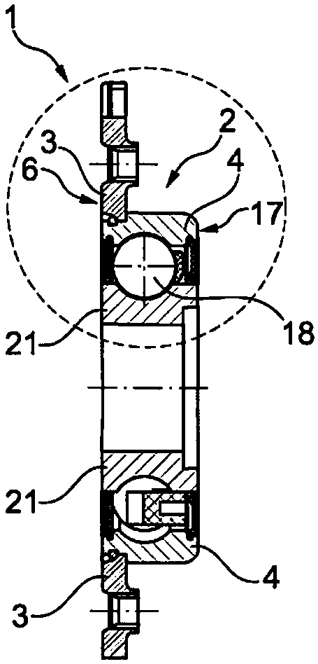
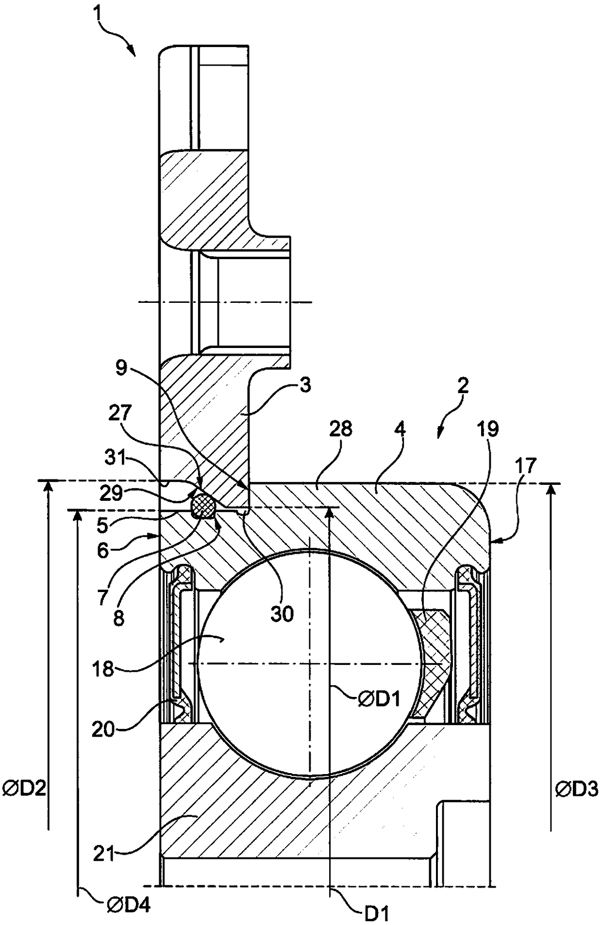
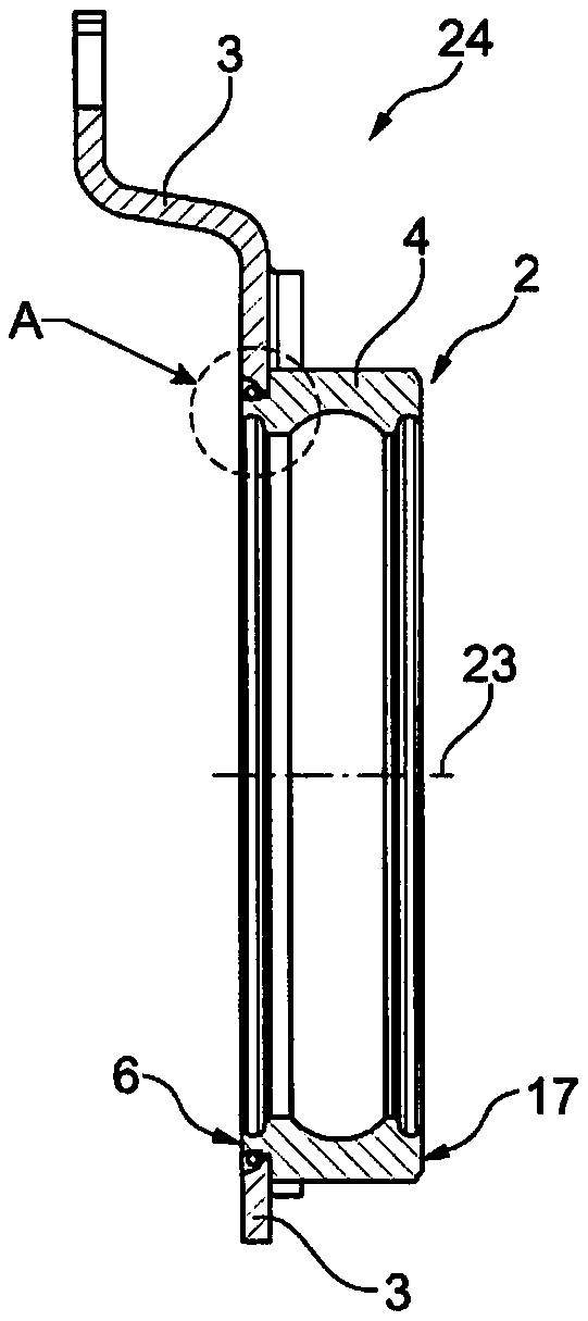
[0035] exist figure 1 and 2 A bearing unit 1 according to the invention is shown in . The bearing unit 1 comprises a rolling bearing 2 and a holding plate 3 as well as a locking element 7 by means of which the holding plate 3 is fixed on the rolling bearing 2 . The rolling bearing 2 has an outer ring 4 and an inner ring 21 , a plurality of rolling bodies 18 being arranged between the inner ring 21 and the outer ring 4 . The rolling bodies 18 are guided by a cage 19 and kept spaced apart from one another. Furthermore, a sealing element 20 is formed on the rolling bearing 2 in order to prevent lubricant from escaping from the rolling bearing 2 .

[0036] The outer ring 4 has a first end side 6 and a second end side 17 opposite the first end side 6 . A shoulder 5 is formed on the side of the outer ring 4 facing the first end side 6 , which shoulder carries the retaining plate 3 . The shoulder 5 is indicated by a radial diameter step 28 . The diameter step 28 is described by...


PUM


Abstract

The invention relates to a bearing unit having a rolling bearing and a retaining plate, wherein a shoulder for accommodating a retaining plate is formed at the outer ring of the rolling bearing, the retaining plate having a wall having a hole, the central axis of the hole is corresponding to the axially oriented bearing axis of the rolling body. The bore is provided with a radial first diameter step, the first diameter step being indicated by the first diameter and the second diameter, wherein the first diameter is smaller than the second diameter, the retaining plate is capable of being fromthe outer ring. The first end side is pushed up, and wherein the retaining plate is fixed at the outer ring of the rolling bearing by means of a locking element, and wherein the retaining plate is flush with the first end side of the outer ring in the mounted state, wherein the shoulder forms a groove for positively receiving the locking element, and wherein a first stop for the retaining plate isformed at the outer ring.

Description

technical field [0001] The invention relates to a bearing unit and a method for producing a bearing unit with a rolling bearing and a retaining plate, wherein a shoulder for receiving the retaining plate is formed on the outer ring of the rolling bearing, the The retaining plate has a wall with a hole whose central axis corresponds to the axially oriented bearing axis of the rolling bearing, the hole being provided with a radial first diameter step, the first diameter step Indicated by the first diameter and the second diameter, wherein the first diameter is smaller than the second diameter, the retaining plate can be pushed up from the first end side of the outer ring, and wherein the retaining plate is The locking element is fastened to the outer ring of the rolling bearing, and wherein the retaining plate is flush with the first end side of the outer ring in the installed state, wherein the shoulder is formed for The groove of the locking element is accommodated in a form-...

Claims


Application Information

Patent Timeline
Patent Type & Authority Applications(China)
IPC IPC(8): F16C35/04F16C33/58F16C43/04F16C35/077
CPCF16C33/58F16C35/04F16C35/077F16C43/045F16C43/04F16C33/586F16C35/045F16C35/067
Inventor 格奥尔格·德拉塞尔安德烈亚斯·诺伊德克曼弗雷德·温克勒
Owner SCHAEFFLER TECH AG & CO KG
Why Eureka
Try Eureka