A rotary reversing valve

A technology of rotary reversing valve and spool, which is applied to valve details, valve devices, multi-way valves, etc., and can solve problems such as component damage, system pressure rise, and fluid flow failure.

Active Publication Date: 2020-02-11
ZHEJIANG SANHUA COMMERCIAL REFRIGERATION CO LTD
View PDF6 Cites 0 Cited by
  • Summary
  • Abstract
  • Description
  • Claims
  • Application Information

AI Technical Summary

Problems solved by technology

During the product reversing process, when the spool rotates to the intermediate position between the first switching position and the second switching position, the two flow channels inside the spool stagger the flow port on the valve body, that is, the two flow channels If the valve core blocks the flow port, the fluid in the system may not be able to circulate, which will cause the system pressure to rise rapidly and cause damage to the components in the system.

Method used


Image

  • A rotary reversing valve
  • A rotary reversing valve
  • A rotary reversing valve

Examples


Embodiment Construction

[0050] In order to enable those skilled in the art to better understand the technical solutions of the present invention, the present invention will be further described in detail below in conjunction with the accompanying drawings and specific embodiments.

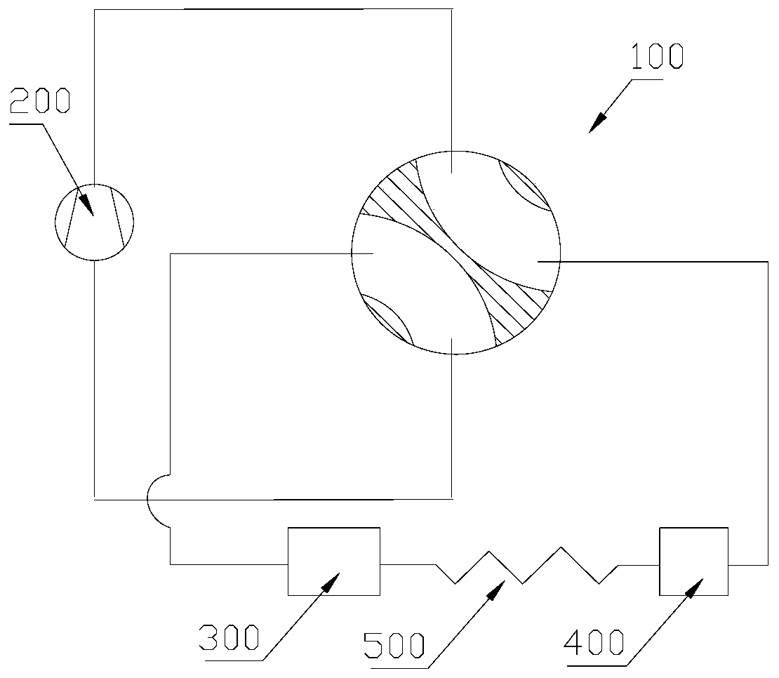
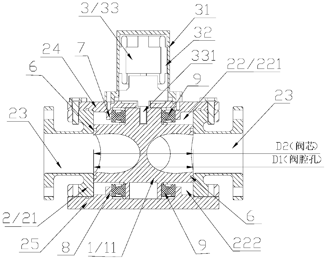
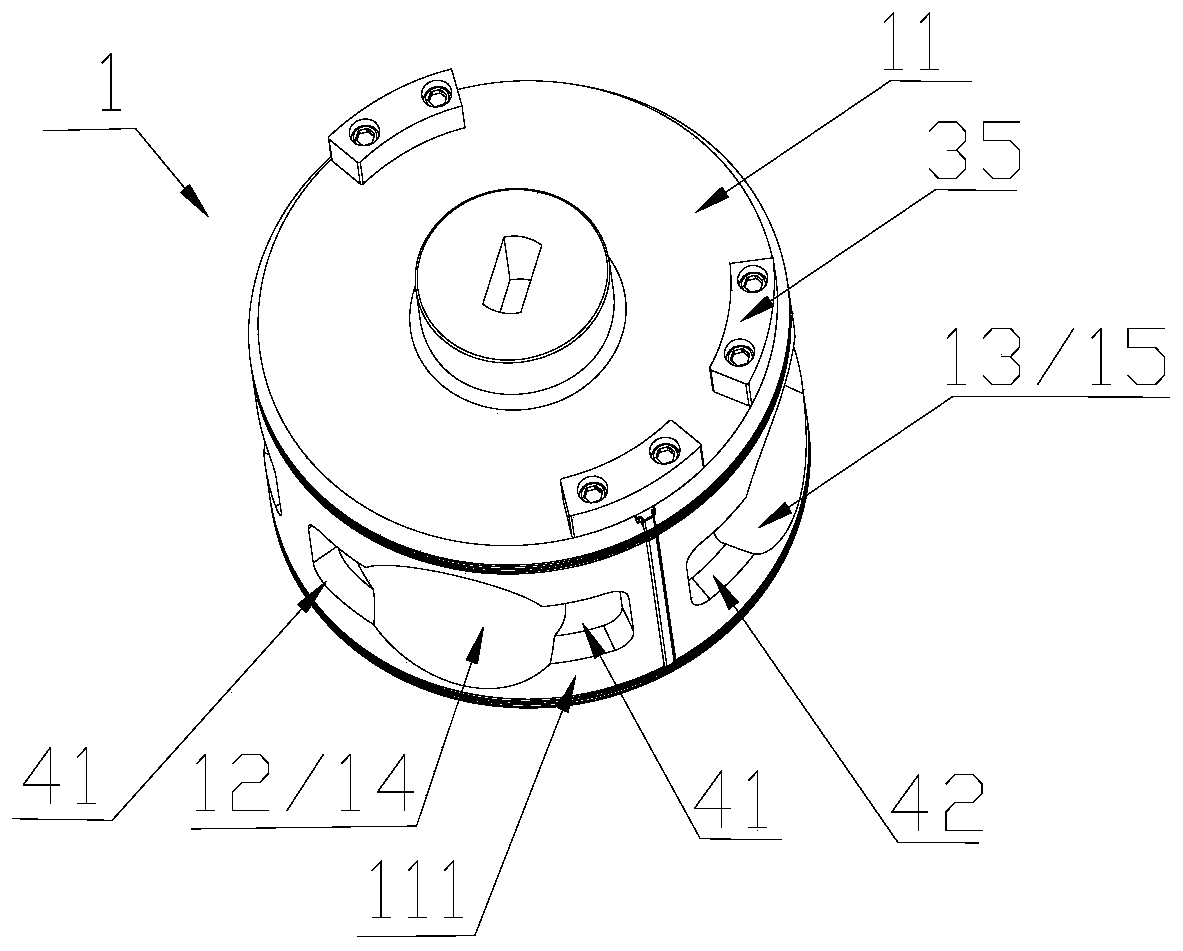
[0051] figure 2 It is a structural schematic diagram of a rotary reversing valve provided by the present invention, image 3 for figure 2The front perspective schematic diagram of the spool part of the medium rotary reversing valve, Figure 4 for figure 2 The side perspective schematic diagram of the spool part of the middle rotary reversing valve, Figure 5 for Figure 4 Schematic diagram of the cross-sectional structure of the middle valve core part in the A-A direction, Image 6 for Figure 5 The enlarged schematic diagram of the structure of the middle spool part in region I.

[0052] Such as figure 2 , image 3 , Figure 4 , Figure 5 and Image 6 shown. In this embodiment, the rotary reversing valve...


PUM


Abstract

The invention discloses a rotary reversing valve. The rotary reversing valve comprises a valve core component, a valve body component and flow guide channels; the valve core component comprises a valve core with a first flow channel and a second flow channel, the first flow channel is provided with two first valve port portions at the circumferential outer edge portion of the valve core, the second flow channel is provided with two second valve port portions at the circumferential outer edge portion of the valve core; the valve body component comprises a valve cavity hole, the inner wall of the valve cavity hole is provided with a plurality of flow path ports; the flow guide channels are arranged between the first flow channel and the flow path ports, and between the second flow channel and the flow path ports, when the valve core is rotated to the middle position of a first switching position and a second switching position, the first flow channel and the second flow channel communicate with the corresponding flow path ports through the flow guide channels correspondingly. According to the disclosed rotary reversing valve, it can be ensured that in the reversing process, a fluid in the system is provided with an open circulation channel so that instant high pressure can not be generated.

Description

technical field [0001] The invention relates to the technical field of refrigeration system control, in particular to a rotary reversing valve. Background technique [0002] In refrigeration systems, reversing valves are generally used to realize the conversion function of cooling and heating. At present, with the development of industry, large-scale refrigeration equipment is constantly being used in the refrigeration industry. The cooling capacity requirements for the reversing valve are also continuously increasing, which requires that the volume of the reversing valve product need to be larger, so the rotary reversing valve with a larger structure is often used to switch the cooling / heating function of the system. [0003] figure 1 It is a schematic structural diagram of a rotary reversing valve used in a refrigeration system in the background art. Such as figure 1 shown. The refrigeration system includes a compressor 200 , a first heat exchanger 300 , a rotary reve...

Claims


Application Information

Patent Timeline
Patent Type & Authority Patents(China)
IPC IPC(8): F16K11/085F16K27/06
CPCF16K11/085F16K27/065
Inventor 不公告发明人
Owner ZHEJIANG SANHUA COMMERCIAL REFRIGERATION CO LTD
Why Eureka
Try Eureka