
Detonator positioning and scanning fixing device

A technology of positioning scanning and fixing device, applied in the direction of electromagnetic radiation induction, etc., can solve the problems of issuing errors, multi-manpower time, and many human factors, and achieve the effect of reducing overall cost, improving safety, and convenient operation.

Pending Publication Date: 2019-03-05
GUANGZHOU BENAN INFORMATION TECH CO LTD
View PDF0 Cites 0 Cited by
  • Summary
  • Abstract
  • Description
  • Claims
  • Application Information

AI Technical Summary

Problems solved by technology

Units with a small amount of detonators use manual distribution, which can basically meet the needs of production. However, for units with a large amount of detonators, if they want to distribute detonators in large quantities in a short period of time, it will take a lot of manpower and a longer time. This is a serious problem. It hinders production efficiency and cannot meet the needs of modern production with rapid development
In addition, the disadvantages of manual distribution of detonators include: (1) It is impossible to efficiently and accurately complete all registration procedures for the distribution of detonators in production; (2) There are many human factors, which may easily cause distribution errors

Method used


Image

  • Detonator positioning and scanning fixing device

Examples


Embodiment Construction

[0024] In order to further understand and recognize the structure, features and effects of the present invention, a preferred embodiment is now given, and detailed descriptions are as follows in conjunction with the accompanying drawings:

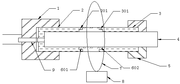
[0025] Such as figure 1 As shown, the detonator positioning mechanism of the present invention includes: a first base 1, a first non-transparent material part 2, a first shoulder 201, a second non-transparent material part 3, a third shoulder 301, and a detonator 4. The second base 5 , the transparent part 6 , the second shoulder 601 , the fourth shoulder 602 , the ring scanner 7 , the supporting frame 8 and the position sensor 9 .

[0026] Such as figure 1 As shown, the sleeve is used to accommodate the detonator 4, and the sleeve includes: a non-transparent material part 3 and a transparent part 6; the non-transparent material part includes: a first non-transparent material part 2 and a second non-transparent material part 3 , the first...


PUM


Abstract

The invention discloses a detonator positioning and scanning fixing device, comprising a tube sleeve, and the sleeve comprising a non-transparent part and a transparent part. The non-transparent partincludes a first non-transparent portion and a second non-transparent portion. The length of the transparent portion matches the distance from the end point of the detonator with one end of the lead to the initiation position of the detonator code. An annular scanner sleeves over the sleeve. The invention ensures the safety of the detonator in the identification coding operation by fixing the position of the detonator in the identification process, and adopts the ring scanner to scan the detonator coding when the detonator is inserted into the pipe sleeve, which has the advantages of simple structure, convenient operation and greatly reducing the comprehensive cost.

Description

technical field [0001] The invention belongs to the technical field of detonator automatic identification, and in particular relates to a detonator positioning, scanning and fixing device for a detonator automatic identification machine. Background technique [0002] The public security department stipulates that the use of detonators must be clearly registered and recorded, indicating the custodian, issuer, recipient, use item, use location, quantity, type, waste, etc. All items are indispensable, and there is a strict use system. [0003] At present, units that use detonators basically manage the use of detonators in accordance with the requirements of the public security department, and the procedures for distributing detonators are also roughly the same, that is, "manual copying, registration, counting, signing, distribution, and archiving." Units with a small amount of detonators use manual distribution, which can basically meet the needs of production. However, for uni...

Claims


Application Information

Patent Timeline
IPC IPC(8): G06K7/10
CPCG06K7/10
Inventor 王沛玉周安法
Owner GUANGZHOU BENAN INFORMATION TECH CO LTD
Learn More