Special measuring ruler for oral cavity gap
A technology for measuring rulers and gaps, which is applied in the fields of medical science and dentistry. It can solve the problems of large size, inability to measure gaps between posterior teeth, and long measurement time. It can improve the reading speed, facilitate one-handed operation, and prevent scratches.
- Summary
- Abstract
- Description
- Claims
- Application Information
AI Technical Summary
Problems solved by technology
Method used
Image

Examples
Embodiment 1
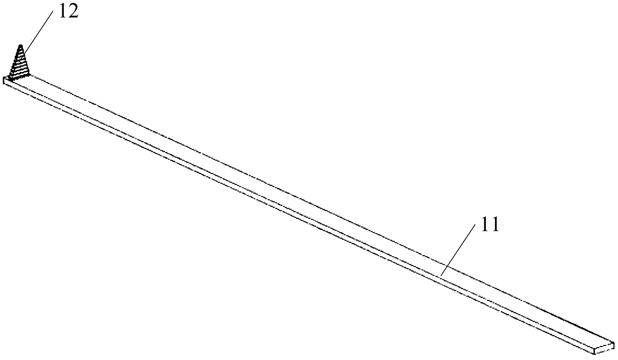
[0031] Such as figure 1 As shown, the special measuring ruler for the oral cavity provided by this embodiment includes a main body 11 and a measuring part 12. The main body 11 is a rectangular parallelepiped made of stainless steel. The length, width and height of the rectangular parallelepiped are 80×2.0×1.0mm. Measuring portion 12 is installed, and described measuring portion 12 is the semi-cone made of stainless steel, and described semi-cone is that the cone is cut in half from the circular midline of the bottom surface along the height direction into any half of the same two halves of shape, The bottom of the semi-cone is fixed on the main body 11 and the radius of the bottom is 1.0mm, and the radius of the top is 0.1mm. Specifically, the arc surface of the semi-cone is aligned with one side of the main body, and the upper edge of the outer wall of the semi-cone is high The direction of the first scale is provided with a first scale, the measurement range of the first sca...
Embodiment 2
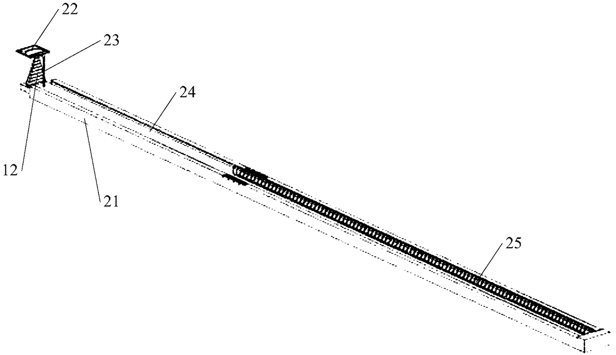
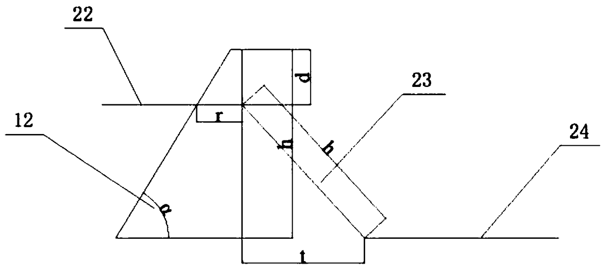
[0035] Such as figure 2As shown, the measuring set ruler for the oral cavity provided in this embodiment includes a first main ruler and a measuring ruler 1, and the first main ruler includes a chute part 21 and a measuring part, and the chute part 21 is a rectangular parallelepiped structure, which The length, width and height are 80×4.0×2.0mm. There is a chute on the top surface. The length, width and height of the chute are 79×2.0×1.5mm. One end of the chute is a closed end and the other end is an open end. Sheet 22, connecting rod 23, transmission rod 24 and spring member 25, transmission rod 24 is movably installed on the chute and does not contact with the bottom of the chute, leaving a gap of 1 mm, and the end of transmission rod 24 close to the closed end of the chute is connected Spring member 25 is arranged, and spring member 25 is by being fixed on the sidewall of closed-end chute, and transmission rod 24 is away from spring member 25 one end and an end of connecti...
Embodiment 3
[0041] The technical solution provided by this embodiment and embodiment 2 is basically the same, only the chute member 21 and the measuring ruler 1 are integrally formed, and a chute can be opened on the plane where the measuring part 12 is installed on the main body 11 of the measuring ruler 1, Installing the measuring piece in the chute can also achieve the same function and effect as in Embodiment 2, and reduce the parts.
PUM
 Abstract
Description
Claims
Application Information
 - R&D
- Intellectual Property
- Life Sciences
- Materials
- Tech Scout
- Unparalleled Data Quality
- Higher Quality Content
- 60% Fewer Hallucinations
Browse by: Latest US Patents, China's latest patents, Technical Efficacy Thesaurus, Application Domain, Technology Topic, Popular Technical Reports.
© 2025 PatSnap. All rights reserved.Legal|Privacy policy|Modern Slavery Act Transparency Statement|Sitemap|About US| Contact US: help@patsnap.com