Novel high-frequency glass cutting head

A high-frequency, new technology, applied in the field of new high-frequency glass cutting head, can solve the problems of large volume, low cutting and suction efficiency, and complex design

Pending Publication Date: 2019-03-08
SUZHOU LIXIANG OPHTHALMIC HOSPITAL CO LTD +1
View PDF0 Cites 5 Cited by
  • Summary
  • Abstract
  • Description
  • Claims
  • Application Information

AI Technical Summary

Problems solved by technology

[0002] At present, in the medical industry, the vitreous body used for eye tissue cutting is generally completed by using a vitreous cutter to cut and absorb the vitreous body. Since the vitreous body in the eye is viscous, in order to achieve this viscous Shaped vitreous, mechanized membrane and blood clots are gradually crushed and removed. Existing vitreous cutters are designed with complex structures, generally double-layered tubes with a high degree of cooperation, and the inner tube reciprocates at high speed during work. The vitreous cutter with a large structure is not only bulky, but also inconvenient to operate, with low cutting and suction efficiency. The effect of cutting and absorbing membranes, lenses and blood clots is not good
At the same time, because the liquid flow is intermittent, it will cause the tissues in the eye to shake greatly, which may easily lead to retinal tear or accidental injury.

Method used


Image

  • Novel high-frequency glass cutting head
  • Novel high-frequency glass cutting head
  • Novel high-frequency glass cutting head

Examples


Embodiment

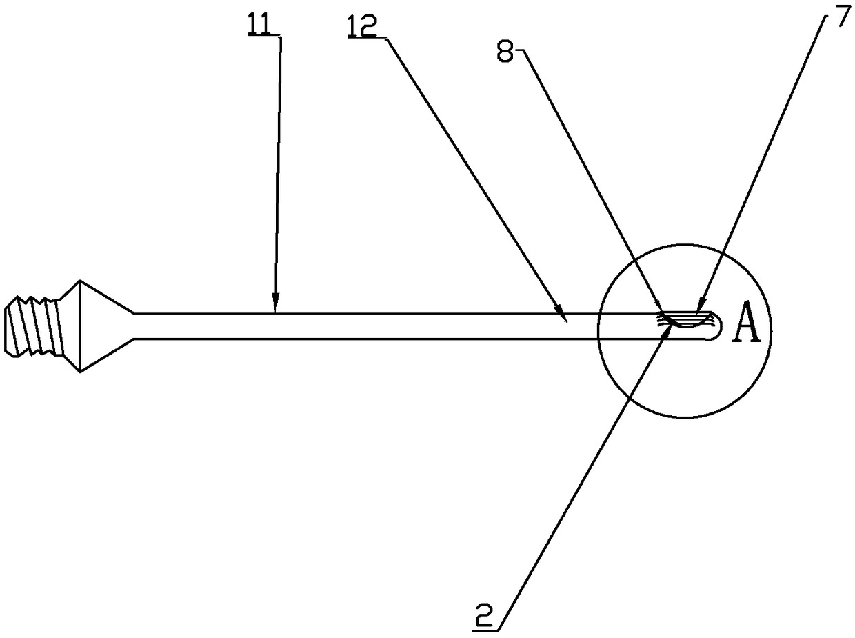
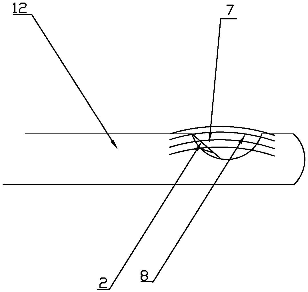
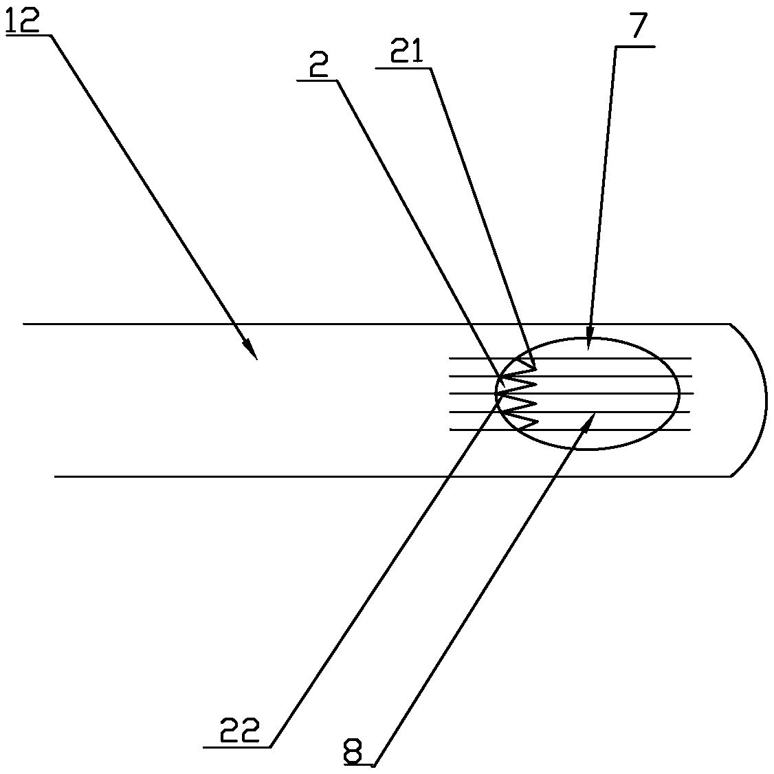
[0024] Such as Figure 1-5 As shown, a novel high-frequency glass cutting head includes an insertion structure, and the insertion structure includes a main body part 11 and a cutting part 12 that are connected to each other in a single-layer pipe-like structure, and the cutting part 12 is arranged on the side of the main body part 11. front end;

[0025] At least one suction hole 7 is provided on the surface of the cutting part 12, and the suction hole 7 communicates with the inner cavity of the insertion structure; a plurality of cutting wires 8 are regularly arranged on the surface of the suction hole 7, and the cutting wires 8 span the Above the suction hole 7, its two ends are fixed on the surface of the cutting part 12, and a zigzag notch 2 is provided at the fracture of the cutting part at the side edge of the suction hole 7, and the zigzag notch 2 includes intervals. The teeth 21 and the alveoli 22, and the cutting wire 8 above the zigzag notch 2 are all located direct...


PUM


Abstract

The invention provides a novel high-frequency glass cutting head. The novel high-frequency glass cutting head comprises an inserting structure, wherein the inserting structure comprises a main body part and a cutting part, the main body part and the cutting part are both single-layer pipeline-shaped structure, the inner portion of the main body part is communicated with the inner portion of the cutting part, and the cutting part is arranged at the front end of the main body part; the surface of the novel high-frequency glass cutting head is provided with a suction hole, and the suction hole iscommunicated with an inner cavity of the inserting structure; the port surface of the suction hole is provided with cutting wires, the cutting wires cross above the suction hole, the fracture portionof the cutting part on the edge of one side of the suction hole is provided with a zigzag notch, the zigzag notch comprises teeth and tooth grooves which are arranged at intervals, and the cutting wires above the zigzag notch are all located right above the tooth grooves; a high-frequency vibration source drives the inserting structure to perform high-frequency vibration on the outer portion, thecutting wires vibrate along with the inserting structure and the amplitude is increased to perform lateral shearing on human tissue in the zigzag notch, when an external negative pressure device works, an inner cavity of the inserting structure forms a negative pressure environment, the human tissue is cut up by the high-frequency vibrating cutting wires, and the cut up human tissue flows to thezigzag notch under the action of surface tension and negative pressure suction and is sucked into the suction hole. The novel high-frequency glass cutting head has the advantages that the suction effect is improved, the operative time is shortened, and complications are reduced.

Description

technical field [0001] The invention relates to the field of medical instruments, in particular to a novel high-frequency glass cutting head. Background technique [0002] At present, in the medical industry, the vitreous body used for eye tissue cutting is generally completed by using a vitreous cutter to cut and absorb the vitreous body. Since the vitreous body in the eye is viscous, in order to achieve this viscous Shaped vitreous, mechanized membrane and blood clots are gradually crushed and removed. Existing vitreous cutters are designed with complex structures, generally double-layered tubes with a high degree of cooperation, and the inner tube reciprocates at high speed during work. The vitreous cutter with a large structure is not only bulky, but also inconvenient to operate, with low cutting and suction efficiency. The effect of cutting and absorbing membranes, lenses and blood clots is not good. At the same time, because the liquid flow is intermittent, it will c...

Claims


Application Information

Patent Timeline
Patent Type & Authority Applications(China)
IPC IPC(8): A61F9/007
CPCA61F9/00754A61F9/00709A61F9/00745A61F9/00763
Inventor 杨勋
Owner SUZHOU LIXIANG OPHTHALMIC HOSPITAL CO LTD
Why Eureka
Try Eureka