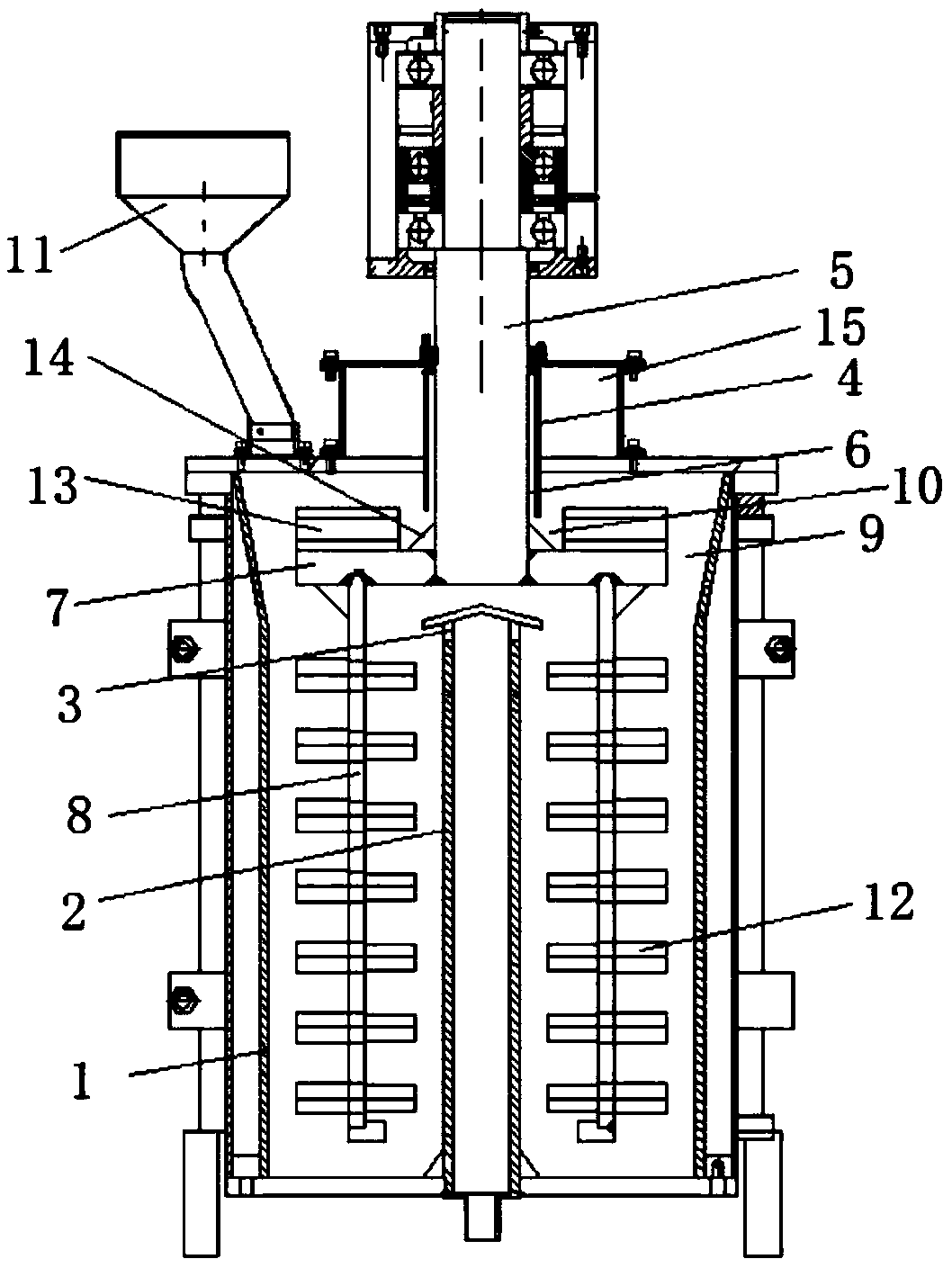
Vertical grinder

A vertical mill and grinding rod technology, applied in the field of construction machinery, can solve problems such as screen blockage and affecting the normal discharge of materials, so as to prevent clogging of pipes and grinding chambers, ensure normal discharge, prevent blockage or pump body. damage effect

Active Publication Date: 2019-03-08
长沙道然智能科技有限公司
View PDF6 Cites 0 Cited by
  • Summary
  • Abstract
  • Description
  • Claims
  • Application Information

AI Technical Summary

Problems solved by technology

In order to ensure that the final grinding particle size of the material meets the specified requirements, the conventional vertical mill is generally designed with a screen at the discharge mechanism, and the material that does not meet the specified particle size is intercepted above the screen to continue grinding until it meets the specified particle size. Large and small materials can fall through the fine holes of the screen to be collected and used. In actual operation, when the vertical mill is used, its inner cavity is often filled with various materials of different thicknesses. At the same time, the materials are often mixed with grinding materials. The media balls, and the materials and grinding media balls tend to accumulate and squeeze on the screen due to gravity, so it is easy to cause the screen to be blocked, which greatly affects the normal discharge of materials

Method used


Image

  • Vertical grinder

Examples


Embodiment Construction

[0016] In order to enable those skilled in the art to better understand the technical solutions in the present application, the technical solutions in the embodiments of the present application will be clearly and completely described below in conjunction with the drawings in the embodiments of the present application. Obviously, the described The embodiments are only some of the embodiments of the present application, but not all of them.

[0017] Based on the embodiments in this application, all other embodiments obtained by persons of ordinary skill in the art without creative efforts shall fall within the scope of protection of this application.

[0018] In the description of the present invention, it should be understood that the orientations or positional relationships indicated by the terms "above", "below", "top", "bottom" etc. are based on the orientations or positional relationships shown in the drawings, and are only for It is convenient to describe the present inve...


PUM


Abstract

The invention discloses a vertical grinder comprising a shell. A feeding pipe penetrating through the interior and the exterior of the shell is arranged on a shell bottom plate, an overflow opening isformed in the upper end of the feeding pipe and is close to the inner wall of the top of the shell, a discharging pipe penetrating through the interior and the exterior of the shell is arranged on ashell top plate, a rotating shaft is inserted into the discharging pipe, a material-guiding channel is formed between the outer wall of the rotating shaft and the inner wall of the discharging pipe, acentrifugal disc is arranged at the lower end of the rotating shaft and located above the overflow opening, grinding rods are arranged on the lower part of the centrifugal disc, a discharging channelis formed between the outer wall of the centrifugal disc and the inner wall of the top of the shell, a groove communicating with the discharging channel is formed in the upper surface of the centrifugal disc and surrounds the periphery of the rotating shaft, the lower part of the material-guiding channel communicates with the groove, and the upper part of the material-guiding channel communicateswith the exterior. Through structural design of the vertical grinder, it can be effectively ensured that materials are normally discharged after being ground.

Description

technical field [0001] The present invention relates to the field of construction machinery, more specifically, to a vertical mill. Background technique [0002] The mill is the key equipment for crushing the material after it is crushed. The mill can be widely used in cement, silicate products, new building materials, refractory materials, chemical fertilizers, non-ferrous metal beneficiation, glass ceramics and other production industries, and can perform dry or wet grinding of various ores and other grindable materials , therefore, mills have been widely used in various industries. Existing mills generally include vertical mills or horizontal mills, among which vertical mills are popular among users because of their small footprint. [0003] A vertical mill generally includes a feeding mechanism, a grinding mechanism, a discharging mechanism, and a driving mechanism. Among them, the grinding mechanism is the main mechanism of the vertical mill, and the design of the gri...

Claims


Application Information

Patent Timeline
Patent Type & Authority Applications(China)
IPC IPC(8): B02C17/16B02C17/20B02C17/24B02C17/18
CPCB02C17/16B02C17/163B02C17/183B02C17/186B02C17/20B02C17/24B02C2017/165
Inventor 万红伟
Owner 长沙道然智能科技有限公司
Why Eureka
Try Eureka