
Power battery main negative relay state detection circuit and method

A technology of main and negative relays and power batteries, which is applied in the direction of circuit breaker testing, instruments, and electrical measurement, and can solve problems such as high cost, safety risks of electric vehicle energy output, and inability to detect main and negative relays.

Active Publication Date: 2019-03-26
华人运通(江苏)动力电池系统有限公司
View PDF17 Cites 16 Cited by
  • Summary
  • Abstract
  • Description
  • Claims
  • Application Information

AI Technical Summary

Problems solved by technology

[0003] In the existing technical solutions, it is generally based on the voltage or current at the front and rear ends of the high-voltage relay to detect whether the high-voltage relays at the positive and negative terminals of the power battery are normally on and off. The method used is mostly to add multiple detection circuits to detect the positive and negative terminals of the power battery. Whether the high-voltage relay is normally on or off, the disadvantage of this method is that the cost is high, and the detection of the state of the main and negative relays cannot be completed before the high-voltage power is turned on, which leads to the safety risk of the energy output of the electric vehicle

Method used


Image

  • Power battery main negative relay state detection circuit and method
  • Power battery main negative relay state detection circuit and method
  • Power battery main negative relay state detection circuit and method

Examples


Embodiment Construction

[0027] In order to make the purpose, technical solutions and advantages of the embodiments of the present application clearer, the technical solutions in the embodiments of the present application will be clearly and completely described below in conjunction with the drawings in the embodiments of the present application. Obviously, the described embodiments are only It is a part of the embodiments of this application, not all of them. The components of the embodiments of the application generally described and illustrated in the figures herein may be arranged and designed in a variety of different configurations. Accordingly, the following detailed description of the embodiments of the application provided in the accompanying drawings is not intended to limit the scope of the claimed application, but merely represents selected embodiments of the application. Based on the embodiments of the present application, all other embodiments obtained by those skilled in the art without...


PUM


Abstract

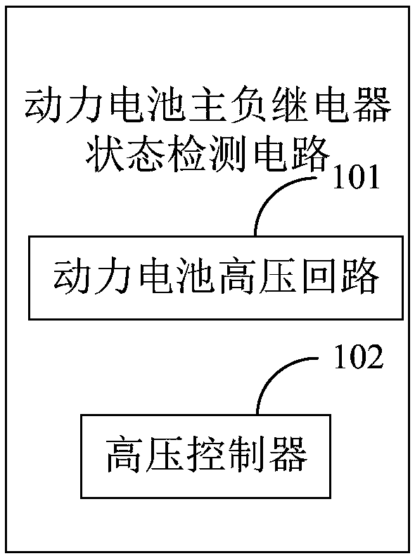
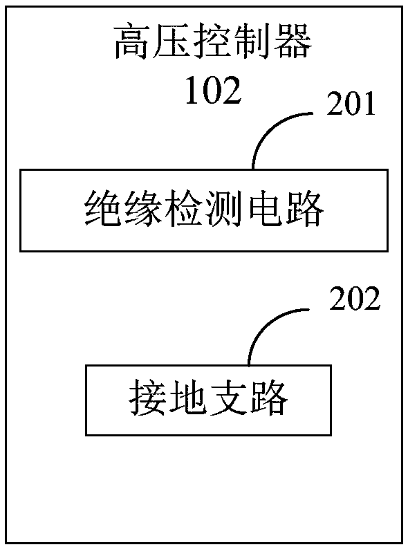
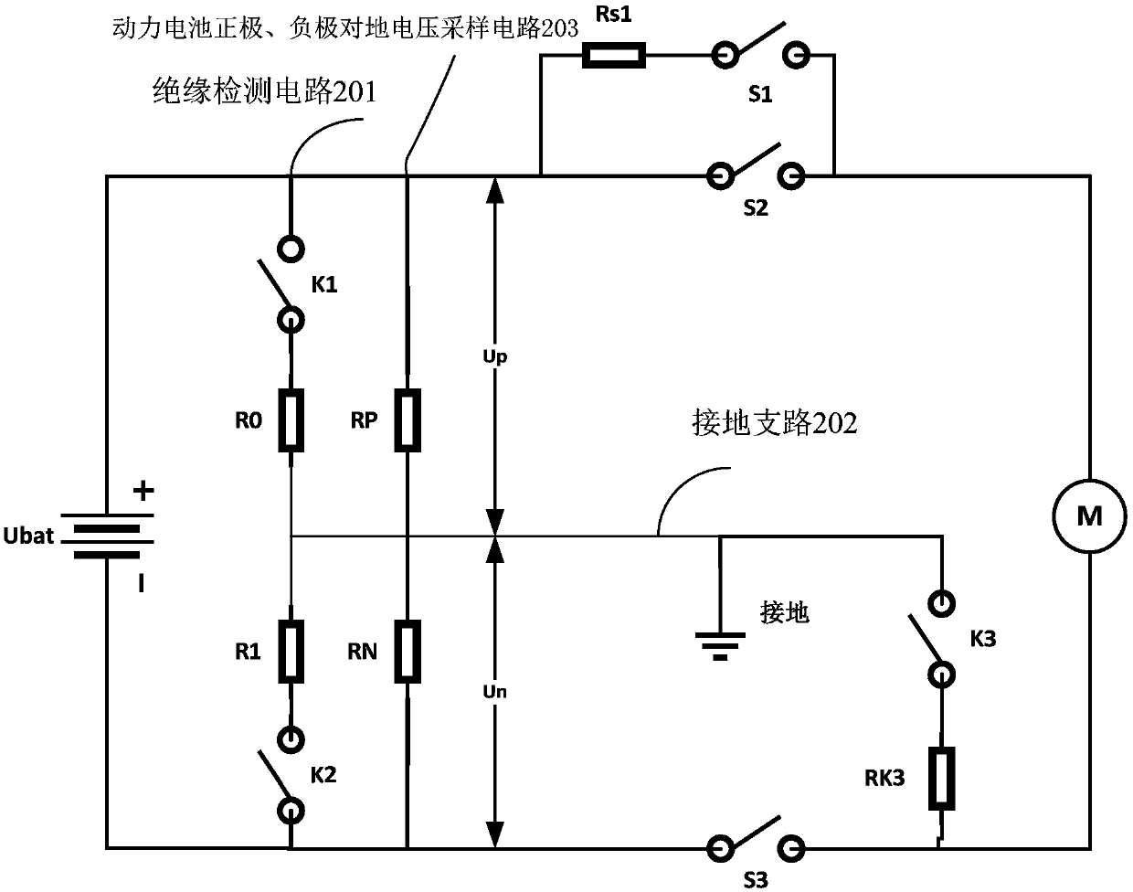
The invention provides a power battery main negative relay state detection circuit and method. The power battery main negative relay state detection circuit comprises a power battery high-voltage circuit and a high-voltage controller, wherein the high-voltage controller includes an insulation detection circuit and a grounding branch circuit, a first terminal of the insulation detection circuit isconnected with the positive electrode of a power battery, a second terminal of the insulation detection circuit is connected with the negative electrode of the power battery, the grounding branch circuit includes a first switch and a test resistor, a first end of the first switch is connected with a third terminal of the insulation detection circuit and grounded, a second end of the first switch is connected with a first end of the test resistor, and a second end of the test resistor is connected with a second end of a negative electrode relay. The invention adopts a method of introducing thegrounding circuit, which is not only simple and feasible but also eliminates unsafe factors in the high-voltage electrifying process of the power battery compared with a method of additionally arranging a plurality of detection circuits and measuring resistors in the prior art.

Description

technical field [0001] The present application relates to the field of electric vehicle high-voltage system control, in particular to a state detection circuit and method for main and negative relays of power batteries. Background technique [0002] The power battery is used as the energy output of the electric vehicle, and its energy output is realized by switching on and off a series of high-voltage devices. The working status of the high-voltage devices, especially whether the positive and negative high-voltage relays of the power battery are normally turned on and off, ensures the energy output of the power battery. very necessary. [0003] In the existing technical solutions, it is generally based on the voltage or current at the front and rear ends of the high-voltage relay to detect whether the high-voltage relays at the positive and negative terminals of the power battery are normally on and off. The method used is mostly to add multiple detection circuits to detect ...

Claims


Application Information

Patent Timeline
Patent Type & Authority Applications(China)
IPC IPC(8): G01R31/327
CPCG01R31/3272G01R31/3275
Inventor 丁磊
Owner 华人运通(江苏)动力电池系统有限公司
Learn More