Energy-saving swirler

A cyclone and distributor technology, which is applied to cyclone devices, devices whose axial directions of cyclones can be reversed, etc., can solve the problems of grading quality fluctuation, large flow rate, and large pressure drop, and achieve a balanced working flow, The effect of reducing operators and increasing service life

Pending Publication Date: 2019-03-08
NANTONG HONGBO MACHINERY
View PDF0 Cites 0 Cited by
  • Summary
  • Abstract
  • Description
  • Claims
  • Application Information

AI Technical Summary

Problems solved by technology

[0003] The purpose of the present invention is to provide an energy-saving cyclone in order to solve the above problems, which solves the problem that the sand pump used for transporting ore pulp in the existing cyclone consumes a lot of power, the inlet and outlet of the sand pump wear severely, the flow rate is too large, and the pressure drops Many, change the feeding st

Method used


Image

  • Energy-saving swirler
  • Energy-saving swirler
  • Energy-saving swirler

Examples


Example Embodiment

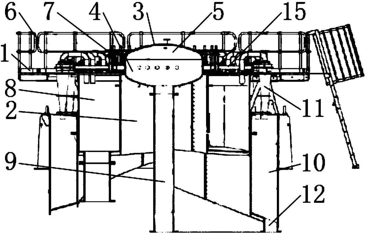
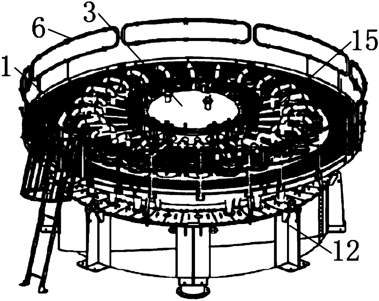
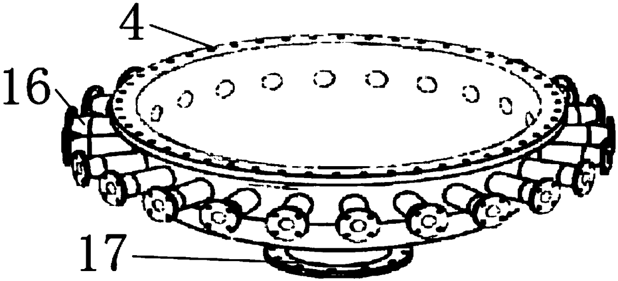
[0026] Such as Figure 1-10 As shown, this specific embodiment adopts the following technical solution: an energy-saving cyclone includes a fixed disk 1, a protective shell 2 is welded to the middle of the lower end of the fixed disk 1, and an overflow groove 8 is welded to the outside of the protective shell 2. A grit tank 10 is welded to the outside of the overflow tank 8, a fence 6 is welded to the periphery of the upper end of the fixed disk 1, and a distributor 3 is welded to the middle of the upper end of the fixed disk 1, and the distributor 3 includes a housing 4 , The outer periphery of the housing 4 is welded with a number of pipes 16, the distance between two adjacent pipes 16 is the same, the upper end of the housing 4 is welded with a distributor cover 5, the upper end of the distributor cover 5 A number of pressure interface flanges 13 are welded, a number of valve bodies 7 composed of manual valves and solenoid valves are provided on one side of the distributor 3...


PUM


Abstract

The invention discloses an energy-saving swirler. The swirler comprises a fixing disc, a protective shell is welded to the middle of the lower end of the fixing disc, an overflow groove is welded to the exterior of the protective shell, a sand trap is welded to the exterior of the overflow groove, a fence is welded to the periphery of the upper end of the fixing disc, and a distributor is welded to the middle of the upper end of the fixing disc; the distributor comprises a shell, a plurality of guide pipes are welded to the periphery of the exterior of the shell, the distances between every two adjacent guide pipes are the same, a distributor cover is welded to the upper end of the shell, a plurality of pressure connector flanges are welded to the upper end of the distributor cover, and aplurality of valve bodies composed of manual valves and electromagnetic valves are arranged on one side of the distributor; and a plurality of diversion devices are arranged at the upper end of the fixing disc, each diversion device comprises fixing shells, and centering linings are adhered to the inner sides of the fixing shells. According to the swirler, lining rubber material in components is changed, so that the service life of the swirler can be greatly prolonged; and pressure connectors are additionally arranged on the distributor cover, so that the use condition of the swirler during working can be better controlled in real time, and the unnecessary damage to the swirler can be avoided.

Description

Technical field: [0001] The invention belongs to the technical field of cyclones, in particular to an energy-saving cyclone. Background technique: [0002] The sand pump used to transport ore slurry in the existing cyclone consumes a lot of power, the inlet and outlet of the sand pump are severely worn, the flow rate is too large, and the pressure drop is large. Change the feeding status or cyclone parameters, 2-stage operation / require large size Cyclone, changing the parameters of the cyclone, the abrasiveness of the feeding material is high, and the manufacturing material needs to be replaced, so repairs are frequent, and the range of feed particle size, pulp concentration and pressure is required to be small, which is likely to cause fluctuations in classification quality. Invention content: [0003] The purpose of the present invention is to provide an energy-saving cyclone in order to solve the above problems, which solves the problem that the sand pump used for trans...

Claims


Application Information

Patent Timeline
IPC IPC(8): B04C5/28B04C5/04B04C5/085
CPCB04C5/04B04C5/085B04C5/28
Inventor 郭严锋毛学伦周建其杨志峰
Owner NANTONG HONGBO MACHINERY
Why Eureka
Try Eureka