A working method of an h-shaped steel automatic welding device

A technology of automatic welding and working methods, applied in welding equipment, auxiliary equipment, auxiliary welding equipment, etc., can solve the problems of high labor intensity of workers, lack of fixing devices, and potential safety hazards of H-beam scrapping, so as to improve welding efficiency and automation High degree, the effect of reducing labor intensity

Active Publication Date: 2020-07-03
南京图信新材料科技有限公司
View PDF6 Cites 0 Cited by
  • Summary
  • Abstract
  • Description
  • Claims
  • Application Information

AI Technical Summary

Problems solved by technology

[0004] Although this invention can weld two H-shaped steels at the same time, it is difficult to weld both sides of an H-shaped steel at one time in this patent, requiring workers to manually change the positions of the H-shaped steels, which brings great trouble to the workers ; Although this patent can lack the fixing device for the H-shaped steel, it is easy to shake or shift the H-shaped steel in the welding process, which affects the success rate of the H-shaped steel welding, and makes the H-shaped steel have a safety hazard of being scrapped; this patent can only One side of the H-shaped steel is welded, and both sides of the H-shaped steel need to be welded, so that the worker needs to manually turn over the H-shaped steel, which will bring greater labor intensity to the worker.

Method used


Image

  • A working method of an h-shaped steel automatic welding device
  • A working method of an h-shaped steel automatic welding device
  • A working method of an h-shaped steel automatic welding device

Examples


Embodiment Construction

[0036] The following will be combined with Figure 1 to Figure 11 The present invention is described in detail, and the technical solutions in the embodiments of the present invention are clearly and completely described. Apparently, the described embodiments are only some of the embodiments of the present invention, not all of them. Based on the embodiments of the present invention, all other embodiments obtained by persons of ordinary skill in the art without making creative efforts belong to the protection scope of the present invention.

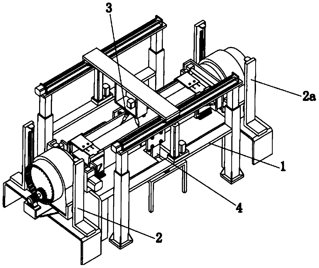
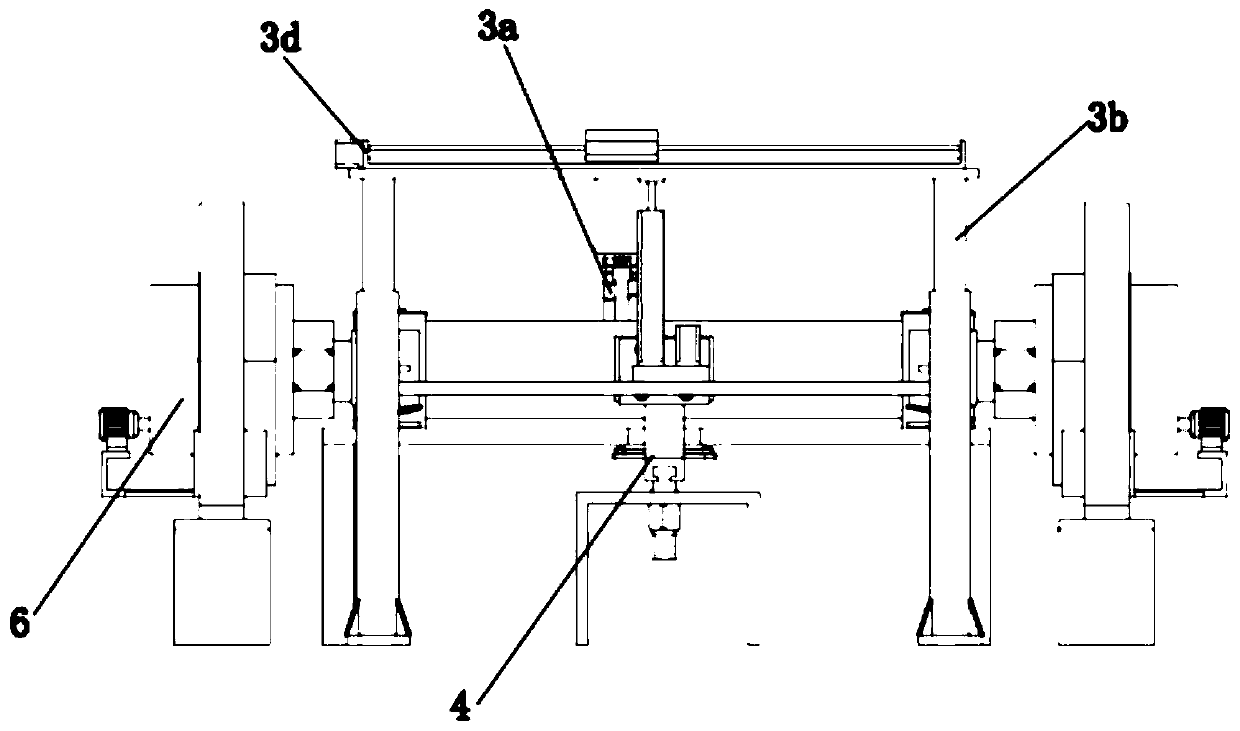
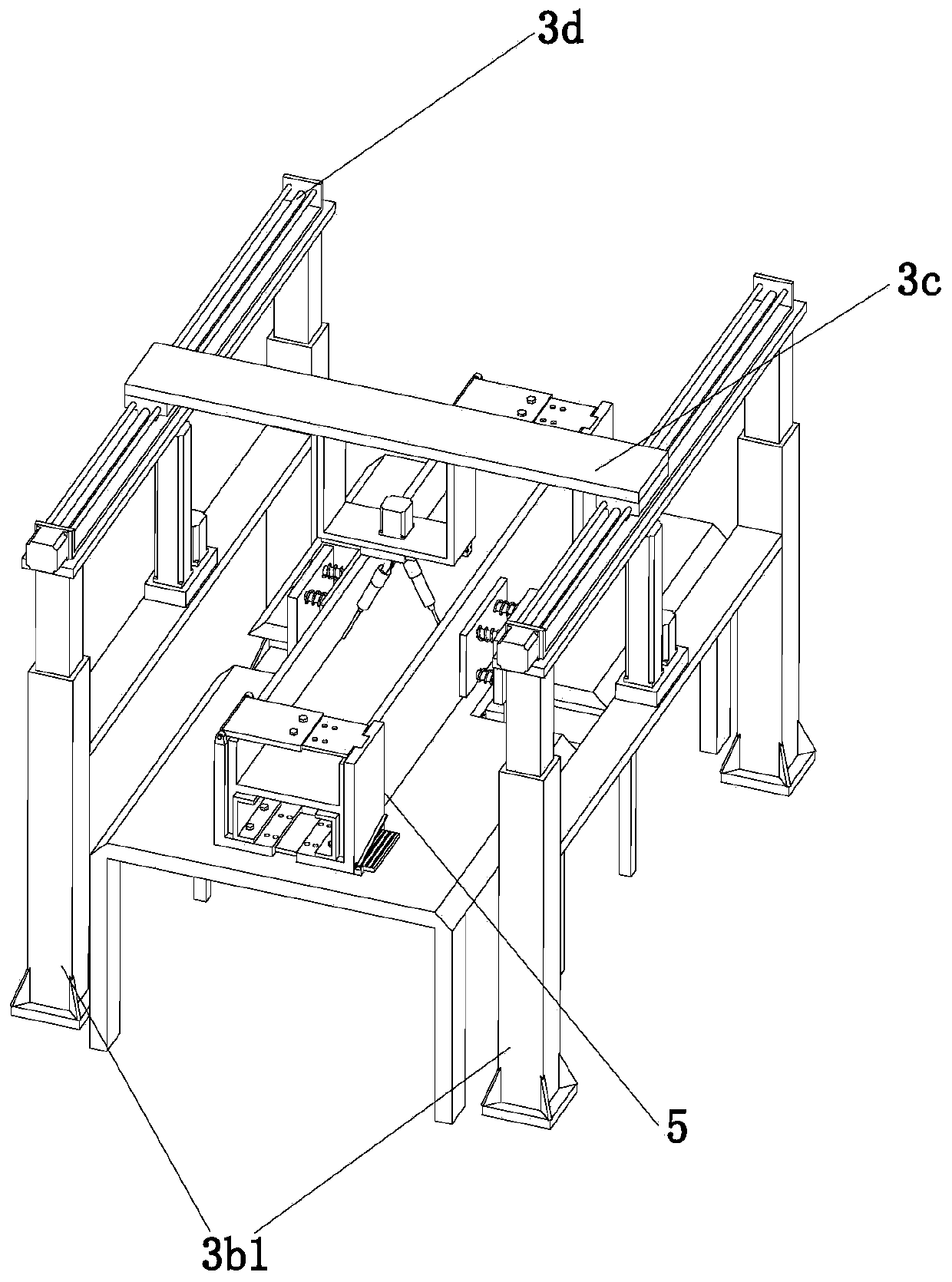
[0037] The present invention provides a kind of H-beam automatic welding device here by improving, as Figure 1-Figure 11 As shown, it includes a workbench 1, a turning mechanism 2, an automatic welding mechanism 3 and a limit mechanism 4. The turning mechanism 2 is arranged on both sides of the workbench 1, and the automatic welding mechanism 3 is arranged on the top of the workbench 1. The position-limiting mechanism 4 is arranged belo...


PUM


Abstract

The invention relates to the field of steel structure machining equipment, in particular to an H-shaped steel automatic welding device. The H-shaped steel automatic welding device comprises a workbench, turnover mechanisms, an automatic welding mechanism and a limiting mechanism; the top of the workbench is provided with two limiting jigs which are arranged in a spaced mode and can move; and the automatic welding mechanism comprises a welding assembly, a lifting assembly, an installation plate and two screw rod sliding tables, and the installation plate is of a cuboid structure. The H-shaped steel automatic welding device has the beneficial effects that to-be-welded positions of the two sides of H-shaped steel can be welded at the same time through the automatic welding mechanism, workersdo not need to change the position of the H-shaped steel additionally, and convenience is brought to the workers; through the limiting mechanism, limiting operation can be automatically conducted on the H-shaped steel, and the H-shaped steel does not deviate in the welding process; and in addition, through the turnover mechanisms, automatic turnover operation of the H-shaped steel can be achieved,the workers do not need to manually carry out turnover operation, and the labor intensity of the workers is relieved.

Description

technical field [0001] The invention relates to the field of steel structure processing equipment, in particular to a working method of an H-shaped steel automatic welding device. Background technique [0002] H-shaped steel is composed of two wings and one web, and has an H-shaped cross-sectional shape; H-shaped steel has the advantages of ideal cross-sectional area distribution and reasonable strength-to-weight ratio, so it has stronger bending resistance than I-shaped steel. Under the same cross-sectional load, H-shaped steel has the characteristics of lower weight than traditional structural steel. The traditional welding method is to place the web horizontally first, and then fix the vertical wing plate in the middle before welding. After welding, the other Weld on both sides of one side. This welding method has many steps, low efficiency, and low degree of automation, and long-term work will bring greater labor intensity to workers. [0003] The patent No. CN10737833...

Claims


Application Information

Patent Timeline
Patent Type & Authority Patents(China)
IPC IPC(8): B23K37/047
CPCB23K37/047
Inventor 何志彦张海亭段瑶瑶
Owner 南京图信新材料科技有限公司
Why Eureka
Try Eureka