Three-valve separated expander

A separate, tire-expanding technology, which is applied in the direction of expanding the mandrel, can solve the problems of forming tool damage, workpiece scrapping, metal fatigue, etc., and achieve the effects of increased service life, cost saving, and stable quality

Inactive Publication Date: 2015-07-29
HEFEI HAOCHENG IND & TRADE
View PDF4 Cites 3 Cited by
  • Summary
  • Abstract
  • Description
  • Claims
  • Application Information

AI Technical Summary

Problems solved by technology

During the processing, if the machining allowance of the workpiece is too large, the cutting force of the workpiece will increase, the inner hole of the product will slip relative to the clamping mechanism, the forming tool will be seriously damaged, and the processed workpiece may be scrapped
In addition, ordinary tires are designed with one end axially divided into three parts and the other end integrated. If it is used for a long time, it will easily cause the metal at the root to fatigue and break.

Method used


Image

  • Three-valve separated expander
  • Three-valve separated expander

Examples


Embodiment Construction

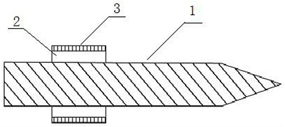
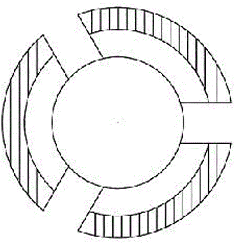
[0014] refer to Figure 1-2 , it includes a shaft (1), characterized in that: one end of the shaft (1) is a three-lobed separated structure, each petal is covered with an expanding core (2), and the expanding core (2) is covered with an expanding sleeve ( 3), the other end of the shaft (1) is a tapered thimble. The three-lobed split structure is symmetrical about the axis (1), and each petal has the same size.

[0015] The invention has low manufacturing cost, very convenient installation and removal of workpieces, and the machine tool can fully implement automatic clamping and loosening work, thereby greatly reducing manual labor intensity. One end is positioned and tightened, and the other end is tightened by the tapered thimble of the tailstock, and both ends of the workpiece are clamped simultaneously. And the three petals are completely separated and there is no problem of breakage. Thereby completely solving all existing problems of the traditional tire-increasing cla...


PUM


Abstract

The invention discloses a three-valve separated expander and relates to the technical field of mineral anchorage clamping piece type products. The three-valve separated expander comprises a shaft (1) and is characterized in that one end of the shaft (1) is of a three-valve separated structure, an expanding core (2) sleeves each valve, an expanding sleeve (3) sleeves each expanding core (2), and a taper center is arranged at the other end of the shaft (1). The three-valve separated structure is in central symmetry relative to the shaft (1), and the valves are same in size. The three-valve separated expander is low in manufacturing cost, facilitates workpiece mounting and taking out, enables machine tools to completely execute automatic clamping and releasing actions, and greatly reduces the labor intensity of manpower.

Description

[0001] technical field [0002] The invention relates to the technical field of processing mine anchor clip products, in particular to a three-lobe separated tire expander. Background technique [0003] The outer conical surface of the mining anchor clip is generally processed by lathe. The traditional workpiece tightening mechanism adopts: one end of the clip is positioned by the end face shaft, and the other end is pushed in by the tailstock taper thimble to implement workpiece clamping. During the processing, if the machining allowance of the workpiece is too large, the cutting force of the workpiece will increase, the inner hole of the product will slip relative to the clamping mechanism, the forming tool will be seriously damaged, and the processed workpiece may be scrapped. In addition, ordinary tires are designed with one end axially divided into three lobes and the other end integrated. If used for a long time, it is easy to cause the metal at the root to fatigue and...

Claims


Application Information

Patent Timeline
Patent Type & Authority Applications(China)
IPC IPC(8): B23B31/40
CPCB23B31/4006B23B31/40
Inventor 不公告发明人
Owner HEFEI HAOCHENG IND & TRADE
Why Eureka
Try Eureka