Connection structure and method of track beam and shield segment

A shield segment and connection structure technology, which is applied in the direction of track, track laying, track maintenance, etc., can solve the problems of difficult plane and vertical adjustment of track beams, unfavorable track beam maintenance and replacement, and inability to pour at the same time, so as to ensure reliable Maintainability and replaceability, simple construction, and low cost

Pending Publication Date: 2019-03-08
CHINA RAILWAY SIYUAN GRP SOUTHWEST SURVEY & DESIGN CO LTD +1
View PDF0 Cites 3 Cited by
  • Summary
  • Abstract
  • Description
  • Claims
  • Application Information

AI Technical Summary

Problems solved by technology

However, the main structure of the shield tunnel is a prefabricated reinforced concrete segment, which cannot be poured simultaneously with the supporting structure of the track beam support. According to the existing connection method, the track beam (wall) and the bottom of the tunnel are poured into an integral structure, and the track The plane and vertical adjustment of the beam will be more difficult, which is not conducive to the maintenance and replacement of the track beam
However, at present, there are no patents and research results on the connection between the support structure of the track beam support in the shield tunnel and the shield segment in China.

Method used


Image

  • Connection structure and method of track beam and shield segment
  • Connection structure and method of track beam and shield segment

Examples


Embodiment Construction

[0023] The specific implementation manners of the present invention will be further described in detail below in conjunction with the accompanying drawings and embodiments. The following examples are used to illustrate the present invention, but are not intended to limit the scope of the present invention.

[0024] In the description of the present invention, it should be noted that unless otherwise specified and limited, the terms "installation", "connection" and "connection" should be understood in a broad sense, for example, it can be a fixed connection or a detachable connection. Connected, or integrally connected; it may be mechanically connected or electrically connected; it may be directly connected or indirectly connected through an intermediary, and it may be the internal communication of two components. Those of ordinary skill in the art can understand the specific meanings of the above terms in the present invention in specific situations.

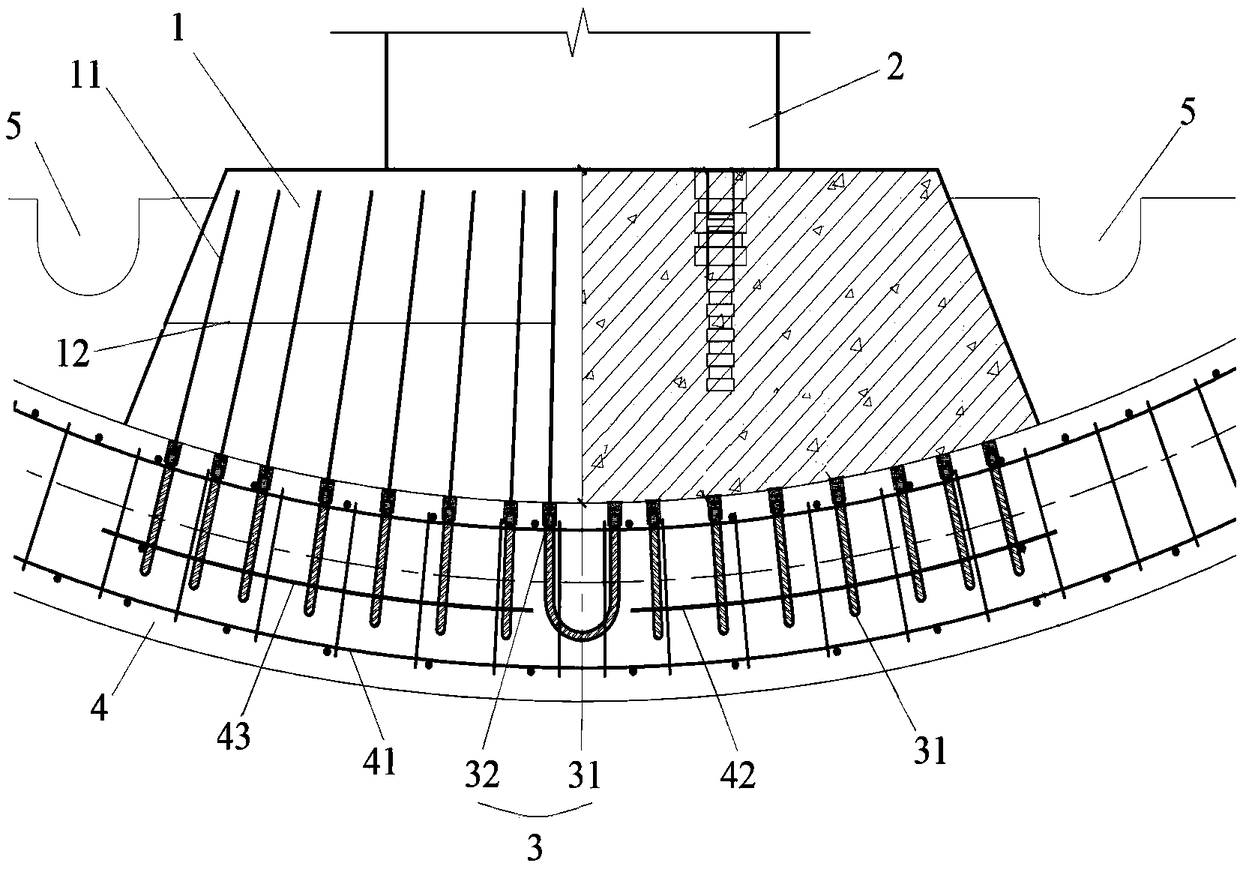
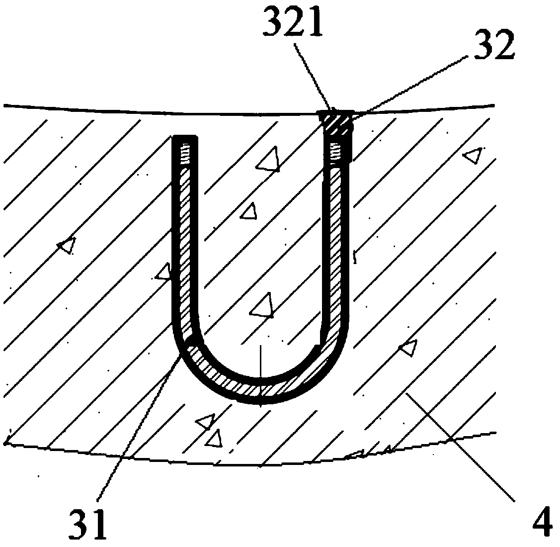
[0025] figure 1 A sche...


PUM


Abstract

The invention relates to the field of monorail traffic engineering, and discloses a connection structure and method of a track beam and a shield segment. The connection structure comprises a pedestalarranged at the bottom of the track beam, two supports arranged on the pedestal separately, and a plurality of embedded members embedded in the shield segment; the two ends of the track beam are detachably connected with the two supports respectively; a plurality of pedestal main ribs are arranged in the pedestal, each pedestal main rib is provided with an extension part which extends out of the end, in butt joint with the shield segment, of the pedestal, and each extension part corresponds to one embedded member and is in threaded fit insertion connection with the corresponding embedded member. By means of the connection structure and method of the track beam and the shield segment, connection of the track beam and the shield segment can be realized, the requirements for strength, rigidity and stability under load transfer of a vehicle and the track beam are met, linear adjustment, maintenance and replacement of the track beam are facilitated, construction is convenient, and the construction cost is low.

Description

technical field [0001] The invention relates to the field of monorail traffic engineering, in particular to a connection structure between a track beam and a shield segment and a connection method thereof. Background technique [0002] At present, straddle-type monorail traffic projects at home and abroad are mainly laid on the ground, generally using a bridge structure, and the track beam bearings are connected to the substructure such as the pier and abutment through supporting pad stones. This technology is mature and widely used. However, in the core area of ​​the city, due to the constraints of ground space, some sections of the straddle monorail need to be laid underground. How to reliably connect the track beam support to the tunnel structure has become one of the key issues in solving the straddle monorail into the ground. . [0003] At present, the construction methods of straddle monorail tunnels are mainly mine method or open cut method. The above two methods are...

Claims


Application Information

Patent Timeline
IPC IPC(8): E01B2/00E01B25/08E01B29/00
CPCE01B2/003E01B25/08E01B29/00E01B29/005E01B2204/09E01B2204/10
Inventor 裴利华曾新平林东杨醒宇贾艳飞
Owner CHINA RAILWAY SIYUAN GRP SOUTHWEST SURVEY & DESIGN CO LTD
Why Eureka
Try Eureka