Combined forming cutter

A technology for cutting tools and jigs, which is applied to lathe tools, manufacturing tools, accessories of tool holders, etc. It can solve the problems that large-diameter workpieces and deep grooves cannot be cut, and only brittle materials can be cut. It is not easy to break the knife, has a wide range of uses, and has the effect of low overall cost

Inactive Publication Date: 2002-11-20
田根旺
View PDF4 Cites 0 Cited by
  • Summary
  • Abstract
  • Description
  • Claims
  • Application Information

AI Technical Summary

Problems solved by technology

[0005] U.S. Patent US2391133 discloses a cutting tool with alternately welded cutter bodies. Although it does not require a sharpening type, it is limited by the large diameter of the workpiece and the depth of the grooving when used, so it cannot cut larger diameter workpieces and deep grooves, and only Can cut brittle materials

Method used


Image

  • Combined forming cutter
  • Combined forming cutter
  • Combined forming cutter

Examples


Embodiment Construction

[0011] The present invention is described in detail as follows with reference to accompanying drawing:

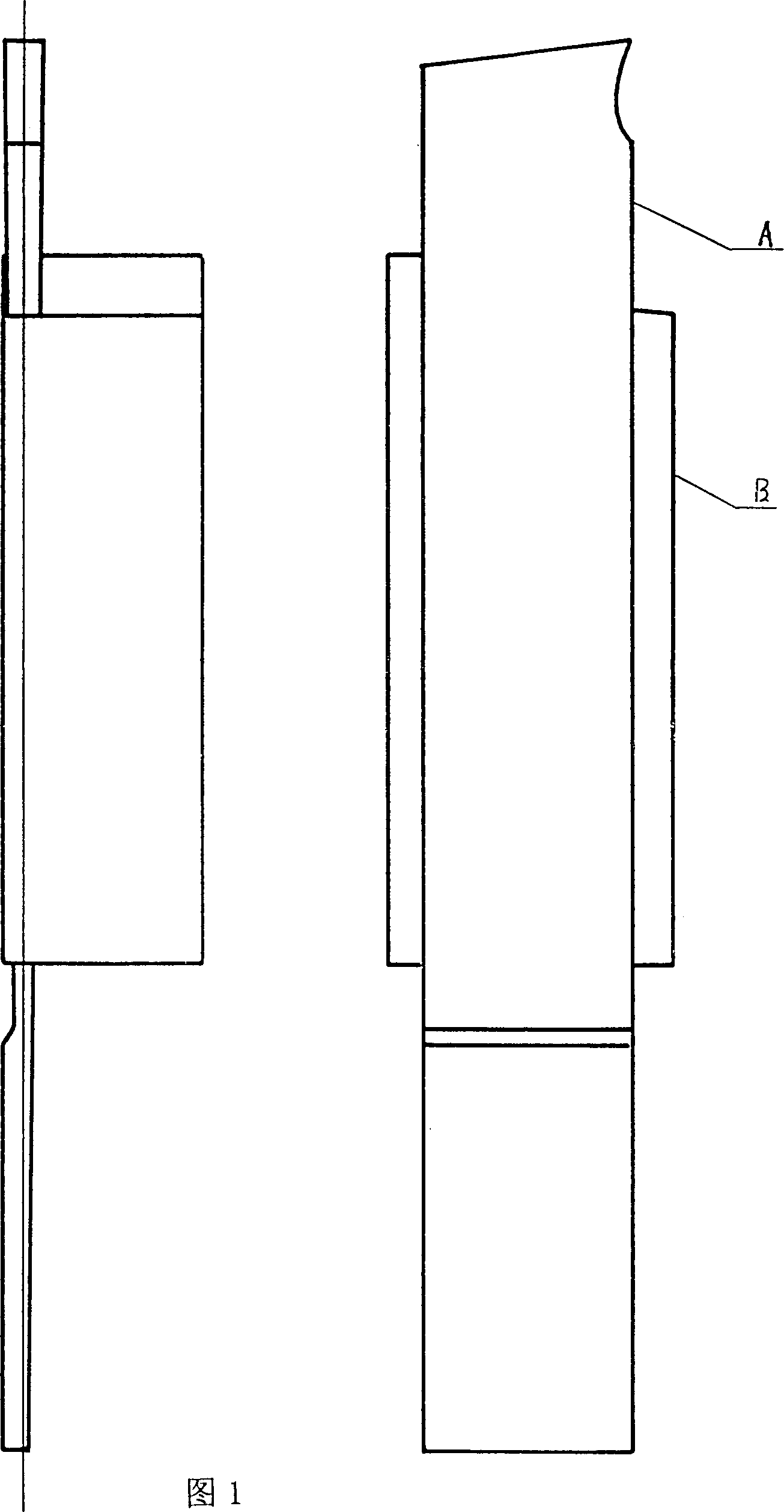
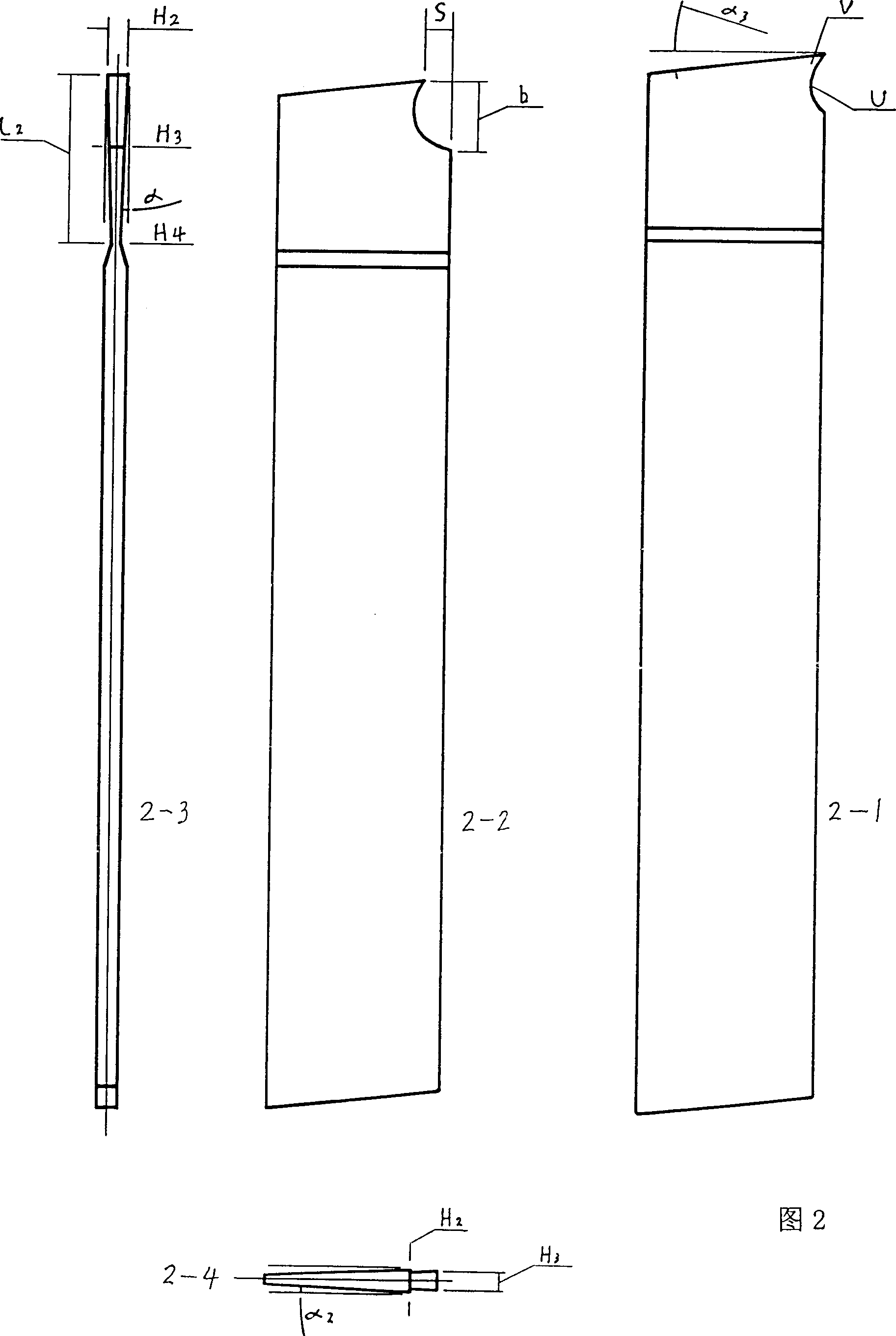
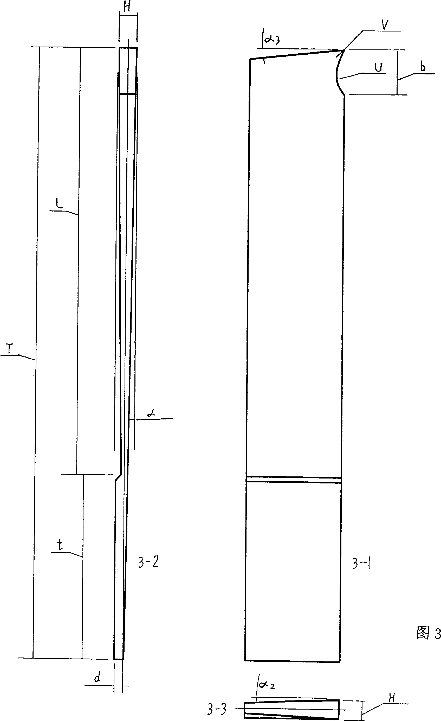
[0012] As shown in the figure, Fig. 1 is the front view and side view of the combined cutting tool with reinforced knife tail shaping, A is the body of the reinforced knife tail cutter, B is the fixture, and the knife body A is inserted into fixture B; Fig. 3 The cutter body shown is composed of two parts, the cutter section L and the cutter tail section t, and there is no transverse angle α in front of the cutter tail section t. 2 , the characteristic is that the longitudinal angle α and the transverse angle α of the existing basic structure of the cutter 2 extended to the full length L of the new blade shape, in order to make H 2 >H 3 Reduce H by appropriately expanding section b 3 , so will never manually grind the longitudinal angle α and transverse angle α 2 knife shape. The success of the design of the reinforced knife tail shaping cutter lies in the addition of ...


PUM


Abstract

The combined forming cutter specially for metal cutting lathe includes cutter comprising cutting section and reinforced tail section and elastic fixture. The cutter is formed wholly, needs no grinding when used,and has long service life. The cutter may be manufactured in different specification for lathe operator to select.

Description

Technical field [0001] The invention relates to the manufacture of a shaped cutting tool for a metal cutting lathe. Background technique [0002] The basic shape of the most commonly used cutting tool for existing metal cutting lathes is a thin sheet shape and long, with a large front end and a small rear end, with a large upper side and a smaller lower side (as shown in Figure 2), and always requires H 2 greater than H 3 , its basic knife shape constitutes a knife shape that is easy to break, but lathe workers have always manually ground steel blocks on the grinding wheel into a section of knife shape for a long time. The low precision results in a higher rate of tool breakage, which causes more troubles to the lathe work and high overall cost, which greatly limits the production of the lathe. [0003] The natural wear of the cutting knife during use causes the rake angle V to change quickly and the wear segment S appears, and gradually expands, due to the longitudinal an...

Claims


Application Information

Patent Timeline
Patent Type & Authority Patents(China)
IPC IPC(8): B23B27/04B23B27/08
Inventor 田根旺
Owner 田根旺
Why Eureka
Try Eureka