
Gate ingot locking device

A lock device and gate technology, applied in water conservancy projects, marine engineering, coastline protection and other directions, can solve the problems of low efficiency, unsafe locking of gates, and high labor intensity, so as to ensure the safety of personnel and improve reliability. performance, prolonging service life

Pending Publication Date: 2019-03-08
四川美姑河水电开发有限公司
View PDF0 Cites 0 Cited by
  • Summary
  • Abstract
  • Description
  • Claims
  • Application Information

AI Technical Summary

Problems solved by technology

[0005] The purpose of the present invention is to provide a gate locking device for the above disadvantages, which is intended to solve the problems of unsafe gate locks, high labor intensity and low efficiency in the existing throwing and withdrawing gates

Method used


Image

  • Gate ingot locking device
  • Gate ingot locking device
  • Gate ingot locking device

Examples


Embodiment 1

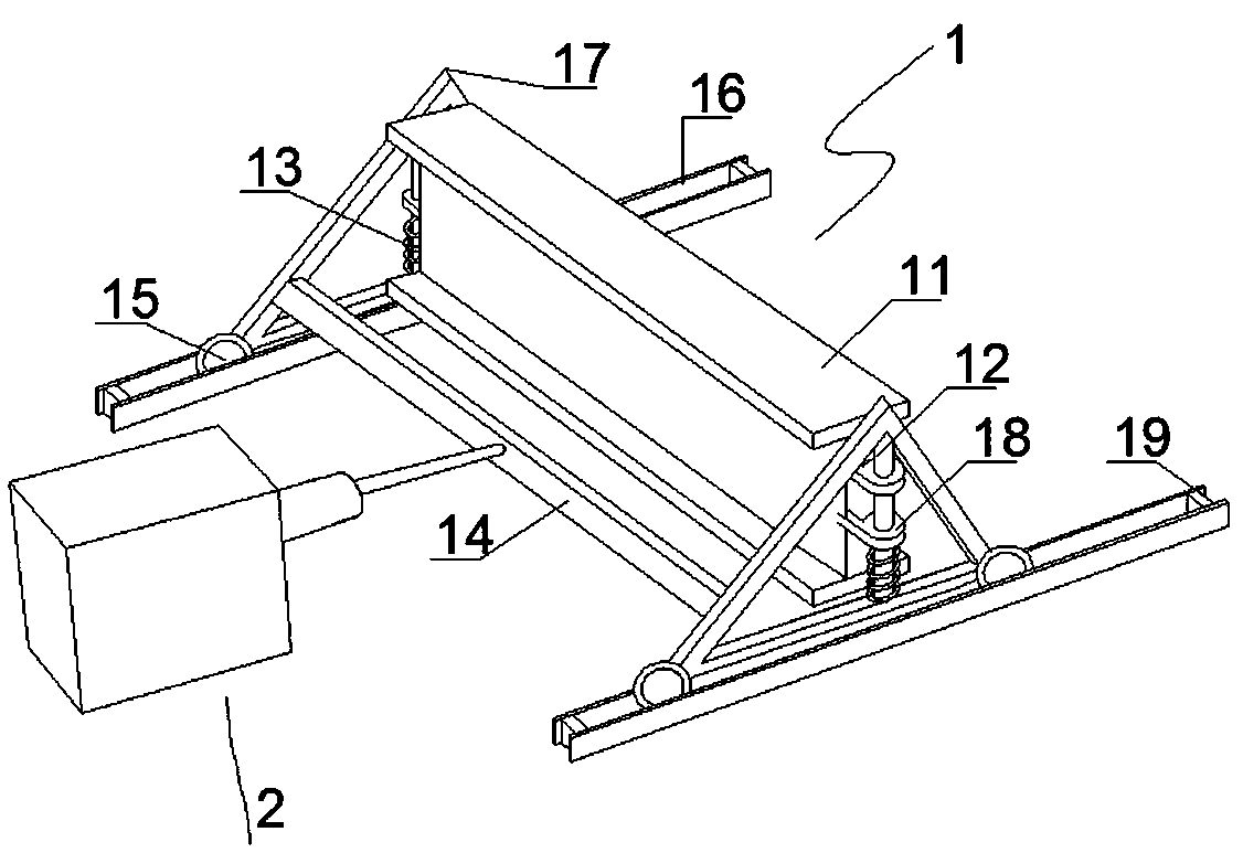
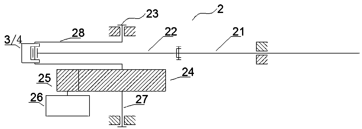
[0023] as attached figure 1 shown. A lock spindle device for a gate, comprising a spindle lock mechanism 1 and a control mechanism 2; the spindle lock mechanism 1 includes an I-beam 11, a guide rod 12, a spring 13, a connecting frame 14, a pulley 15, a slide rail 16 and two sliding Bracket 17; The two sides of described I-beam 11 are provided with outwardly protruding hole ear 18; Described hole ear 18 can move up and down to pass through guide bar 12 that is vertically fixed on the sliding bracket 17, and its lower part presses On the spring 13 pierced on the guide rod 12, the I-beam 11 is separated from the base surface; the lower part of the sliding bracket 17 is provided with a pulley 15 that can move left and right along the slide rail 16; the two sliding brackets 17 are connected by The frame 14 is fixedly connected; the control mechanism 2 is used to push and pull the connecting frame 14 to make it move left and right. The sliding bracket 17 is a triangular bracket, a...

Embodiment 2

[0026] as attached figure 1 shown. A lock spindle device for a gate, comprising a spindle lock mechanism 1 and a control mechanism 2; the spindle lock mechanism 1 includes an I-beam 11, a guide rod 12, a spring 13, a connecting frame 14, a pulley 15, a slide rail 16 and two sliding Bracket 17; The two sides of described I-beam 11 are provided with outwardly protruding hole ear 18; Described hole ear 18 can move up and down to pass through guide bar 12 that is vertically fixed on the sliding bracket 17, and its lower part presses On the spring 13 pierced on the guide rod 12, the I-beam 11 is separated from the base surface; the lower part of the sliding bracket 17 is provided with a pulley 15 that can move left and right along the slide rail 16; the two sliding brackets 17 are connected by The frame 14 is fixedly connected; the control mechanism 2 is used to push and pull the connecting frame 14 to make it move left and right. The sliding bracket 17 is a triangular bracket, a...


PUM


Abstract

The invention discloses a gate ingot locking device, and belongs to the field of hydropower station gate fittings. The gate ingot locking device comprises a ingot locking mechanism and a control mechanism; the ingot locking mechanism comprises I-steel, a guide rod, a spring, a connecting frame, a pulley, a sliding rail and two sliding supports, wherein the two sides of the I-steel are provided with hole lugs which protrude outwards; and the hole lugs can move up and down and penetrate through the guide rod which is vertically fixed on the sliding supports, and the lower portion of a steel baris pressed on the spring arranged on the guide rod in a penetrating mode, so that the I-shaped steel is separated from the base surface; pulleys which can move left and right along the sliding rail are arranged on the lower portions of the sliding supports; and the two sliding supports are fixedly connected through the connecting frame, and the control mechanism is used for pushing and pulling theconnecting frame to move left and right. The gate ingot locking device can realize automatic feeding and withdrawing of an ingot, the safety of personnel is guaranteed, the service life of a winch isprolonged, and the normally-open reliability of a gate is improved.

Description

technical field [0001] The invention belongs to the field of gate fittings of hydropower stations, and in particular relates to a gate locking device. Background technique [0002] The gates of hydropower stations are usually hoisted by winches. The existing lock spindles of gates are I-beams that have been stored in advance manually. The operating time is extended to extend the service life of the hoist and improve the reliability of the gate's normal opening. [0003] Since the incoming water in the river basin during the flood season is mainly affected by rainfall, the flow rate of the incoming water fluctuates greatly. During the flood season, it is necessary to make preparations for shutdown and peak avoidance at any time. Shutdown and peak avoidance generally occur in extreme weather conditions such as heavy rains, and the on-duty personnel must complete the switching and withdrawing of the gate lock while cooperating with the gate lifting operation in the gate hoisti...

Claims


Application Information

Patent Timeline
IPC IPC(8): E02B7/36
CPCE02B7/36
Inventor 刘彪
Owner 四川美姑河水电开发有限公司
Learn More