Submarine steam generator missile ejection system

a steam generator and submarine technology, applied in the field of missile ejection systems, can solve the problems of large and complex high pressure air systems, increased safety concerns of explosive ordnance, and significant costs for safe transportation, so as to reduce energy consumption and ensure personnel safety

Inactive Publication Date: 2008-11-18
UNITED STATES OF AMERICA NAVAL UNDERSEA WARFARE CENT DIV NEWPORT OFFICE OF COUNSEL THE
View PDF28 Cites 2 Cited by
  • Summary
  • Abstract
  • Description
  • Claims
  • Application Information

AI Technical Summary

Benefits of technology

[0023]The pressure vessel is sized for the swept volume needed to provide a saturated steam ejection pulse for the heaviest payload and / or multiple ejection pulses supporting a missile salvo launch. The pressure vessel is encapsulated in an insulating jacket to reduce energy consumption and to ensure personnel safety.

Problems solved by technology

The high pressure air systems were large and complex due to requirements for air flasks, piping and associated isolation valves.
However, ordnance gas generators have brought the added burden of explosive ordnance safety concerns.
These safety concerns include significant costs for safe transport; bunkering and test firings to ensure explosive grain stability and safe ejection performance.
Additional costs for aging / performance of the grain using analysis and live fire tests are expensive.
Also, when gas generators reach the expected acceptable performance end of life, the generators must be disposed at a typically high cost due to explosive and hazardous material.
Overall, the cost in labor, analysis, documentation and logistical storage and transport needed to support current gas generator technology is significant.
However, the cited reference does not describe a static pressure vessel that contains water at high temperature and pressure until a firing valve allows an explosive release of pressure, thus flashing the water to steam and providing thrust for missile ejection.
However, the cited reference is not designed as a unitary pressure vessel missile steam ejection launching source.

Method used


Image

  • Submarine steam generator missile ejection system
  • Submarine steam generator missile ejection system

Examples


Embodiment Construction

)

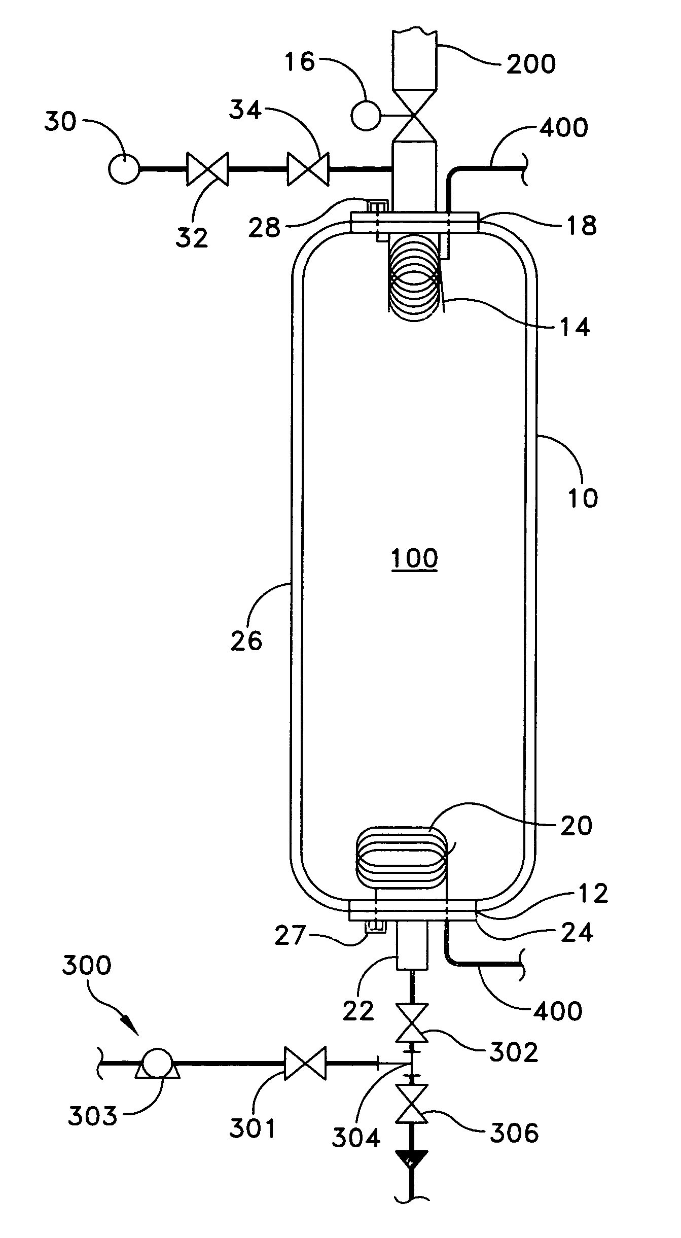
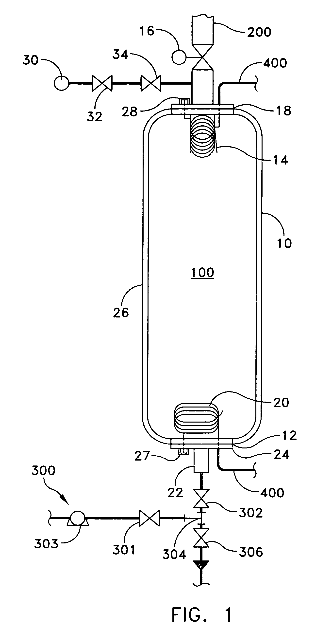
[0028]Referring now to FIG. 1, the submarine steam generator missile ejection system (SSGMES) of the present invention primarily comprises a pressure vessel 10 that contains heated and pressurized water 100 that becomes the steam source for missile ejection. An electrical resistance heating system having a first stage heater 20 and a second stage heater 14 contained inside the pressure vessel 10 heats the water 100 to the desired temperature and launch pressure.

[0029]The SSGMES also includes an ejection system firing valve 16 that isolates the pressure vessel 10 to direct the steam ejection pulse to an ejection discharge header 200 and onto the bottom / ejection chamber of a launch tube (not shown). A de-mineralized water filling and drain system 300 is used to fill or drain the pressure vessel 10.

[0030]The pressure vessel 10 is preferably weldment constructed of stainless steel (certified for high temperature / pressures); however, other suitable materials known to those ordinarily sk...


PUM


Abstract

A steam generator missile ejection system has a vessel that contains water that becomes the pressurized steam source for missile ejection. A heating system within the vessel heats the water to steam and to the desired launch pressure. The heater is controlled to sequence operation and heat generation with a command from a controller shortly before initiation of a firing valve. A valve controls piping from the vessel to direct steam to a piping header and onto the ejection chamber of a launch tube. This event provides the launch pulse required to eject the payload from the missile tube. The launch energy requirements can be modulated by varying the pre-launch temperature of the water in the pressure vessel and can be controlled by an opening rate and length of open duration of the valve.

Description

STATEMENT OF GOVERNMENT INTEREST[0001]The invention described herein may be manufactured and used by or for the Government of the United States of America for governmental purposes without the payment of any royalties thereon or therefor.BACKGROUND OF THE INVENTION[0002](1) Field of the Invention[0003]The present invention relates to a missile ejection system and more particularly to an ejection system using steam as a prime mover or dynamic force to eject a missile.[0004](2) Description of the Prior Art[0005]Current naval missile ejection systems are totally reliant on ordnance gas generators. Ordnance gas generators produce a hot exhaust gas via a controlled propellant burn that provides the dynamic force used to eject the missile from a missile launch tube or capsule.[0006]The ordnance gas generator was preceded in early launching systems by a high pressure air systems. The high pressure air systems were large and complex due to requirements for air flasks, piping and associated ...

Claims


Application Information

Patent Timeline
Patent Type & Authority Patents(United States)
IPC IPC(8): F41F3/00F41B11/00
CPCF41F3/10
Inventor PELTO, JOHN H.
Owner UNITED STATES OF AMERICA NAVAL UNDERSEA WARFARE CENT DIV NEWPORT OFFICE OF COUNSEL THE
Why Eureka
Try Eureka