Eureka AIR delivers breakthrough ideas for toughest innovation challenges, trusted by R&D personnel around the world.

A Method for Strengthening the Concrete Strength of Beam Supports

A technology of concrete strength and reinforcing beams, applied in construction, building maintenance, building construction, etc., can solve the problems of prestress lag, increase structural self-weight, structural aging, etc., to reduce the peak internal force, improve bearing capacity, and improve bending resistance. Effect

Active Publication Date: 2020-12-01
HUAIHAI INST OF TECH
View PDF10 Cites 0 Cited by
  • Summary
  • Abstract
  • Description
  • Claims
  • Application Information

AI Technical Summary

Problems solved by technology

[0002] Structural parts need to be reinforced under the following circumstances: (1) In actual engineering, the concrete often fails to reach the design strength; (2) The design standards of existing old buildings are low, the bearing capacity is insufficient, and the structure is aging, resulting in prestress hysteresis. Structural damage is relatively large; (3) function changes, such as: classrooms become libraries; (4) post-earthquake repairs
The existing reinforcement methods are: (1) Enlarging the section method, the disadvantage is that the self-weight of the structure itself is increased, and the stiffness distribution of the structure itself may also be changed, resulting in chain reinforcement of other adjacent components; (2) The cladding steel reinforcement method , the disadvantage is high cost and complicated construction; (3) the disadvantage of adhesive anchor plate reinforcement is the limitation of the scope of application, and the reinforcement effect depends to a large extent on the bonding process and operation level; (4) the carbon fiber reinforcement method, the disadvantage The quality of the finish largely depends on the selection of carbon fiber cloth and special structural adhesive

Method used


Image

  • A Method for Strengthening the Concrete Strength of Beam Supports
  • A Method for Strengthening the Concrete Strength of Beam Supports
  • A Method for Strengthening the Concrete Strength of Beam Supports

Examples


Embodiment 1

[0041] A method for strengthening the concrete strength of a beam support, the steps are as follows:

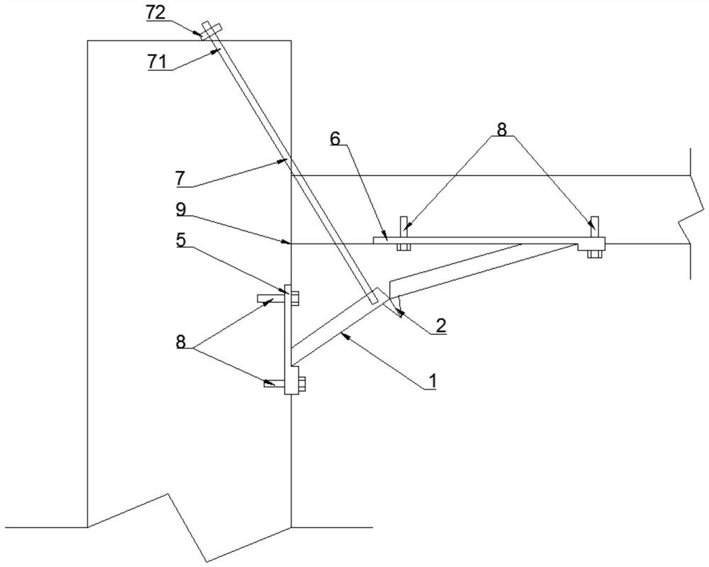
[0042] (1) Refer to figure 1 The lower thrust anchor plate 5 is fixedly installed on the side of the support 220mm below the beam support node 9, the upper thrust anchor plate 6 is fixedly installed on the lower part of the beam 604mm away from the beam support node 9, and the upper and lower thrust The anchor plates are all provided with thrust grooves, the upper thrust groove 61, the lower thrust groove 51 and the node of the beam support form a right-angled triangle reinforcement area, and the angle between the line connecting the upper and lower thrust grooves and the beam is 20°;

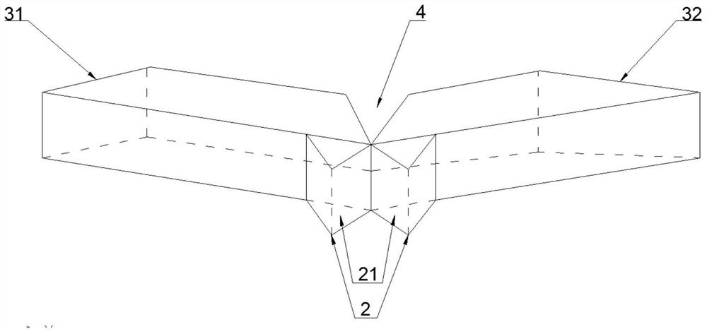
[0043] (2) Refer to figure 2 , to prepare pre-bent channel steel, get a section of channel steel 1, the channel steel type used in the present embodiment is 12, the size is h120mm b53mm d5.3mm, and its length is 648mm, the two ends of channel steel 1 are cut off the flange respectively, One e...

Embodiment 2

[0047] The fixing method of the upper and lower thrust anchor plates has the following steps:

[0048] (1) Excavate the concrete protective layer at the installation position of the upper and lower thrust anchor plates;

[0049] (2) Apply structural adhesive to the mounting surface of the thrust anchor plate. The structural adhesive used in this example is sj168 silicone weather-resistant sealant, and the thickness of the structural adhesive is 5-7mm. Paste the thrust anchor plate on the on the beam support.

[0050] (3) After 2-3 hours, the structural glue is basically hardened to produce enough sticky force, and the reinforcement glue is injected into the installation hole of the thrust anchor plate, and then the bolt 8 is implanted and tightened. The bolts used in this embodiment are M16*80, curing and curing.

Embodiment 3

[0052] refer to figure 2 , the notch of the pre-bending groove 4 in this embodiment is triangular.


PUM


Abstract

The invention discloses a method for reinforcing the strength of beam support concrete. The method comprises the following steps that an upper thrust anchor plate and a lower thrust anchor plate whichare provided with thrust grooves are fixedly mounted on a beam support, a right-triangle reinforcing area is formed by the upper thrust groove, the lower thrust groove and a joint of the beam support, and the included angle between the connecting line of the upper thrust groove and the lower thrust groove and a beam is 15-45 degrees; pre-bent channel steel is prepared, the wing edges of the two ends of the channel steel are cut off, pre-bent grooves are formed in the middles of the wing edges of the channel steel, the channel steel is pre-bent at a groove opening towards the groove opening, and two check anchor blocks are welded to the back face of the channel steel; the two ends of the pre-bent channel steel are mounted in the corresponding upper thrust groove and the corresponding lowerthrust groove, the pre-bent channel steel is tensioned upwards through a tensile rod arranged between the beam and the pre-bent channel steel until the check slopes of the two check anchor blocks arein full contact, the channel steel is fixed, and the pre-bent grooves are welded; and formworks are arranged on the two sides of the right-triangle reinforcing area and filled with the expansive concrete in a poured mode, after the concrete is hardened, the formworks are removed, and the check anchor blocks are cut off. According to the method, under the premise of basically not increasing the load of an original structure, the bending and shear resistance of the support can be greatly improved.

Description

technical field [0001] The invention relates to the field of civil engineering, in particular to a method for strengthening the concrete strength of a beam support. Background technique [0002] Structural parts need to be reinforced under the following circumstances: (1) In actual engineering, the concrete often fails to reach the design strength; (2) The design standards of existing old buildings are low, the bearing capacity is insufficient, and the structure is aging, resulting in prestress hysteresis. Structural damage is relatively large; (3) function changes, such as: classrooms become libraries; (4) post-earthquake repairs. The existing reinforcement methods are: (1) Enlarging the section method, the disadvantage is that the self-weight of the structure itself is increased, and the stiffness distribution of the structure itself may also be changed, resulting in chain reinforcement of other adjacent components; (2) The cladding steel reinforcement method , the disadv...

Claims


Application Information

Patent Timeline
Patent Type & Authority Patents(China)
IPC IPC(8): E04G23/02
CPCE04G23/0218
Inventor 田安国胡文硕陈舜禹姚锦文李青松
Owner HUAIHAI INST OF TECH
Why Eureka
Eureka Blog
Learn More