Auxiliary locking device
A technology of auxiliary locks and transmission plates, which is applied to building locks, devices to prevent keys from being removed from locks, and door/window accessories. It can solve problems such as inconvenient installation, damage, and deformation, and achieve convenient and fast use. speed-up effect
- Summary
- Abstract
- Description
- Claims
- Application Information
AI Technical Summary
Problems solved by technology
Method used
Image
Examples
Embodiment 1
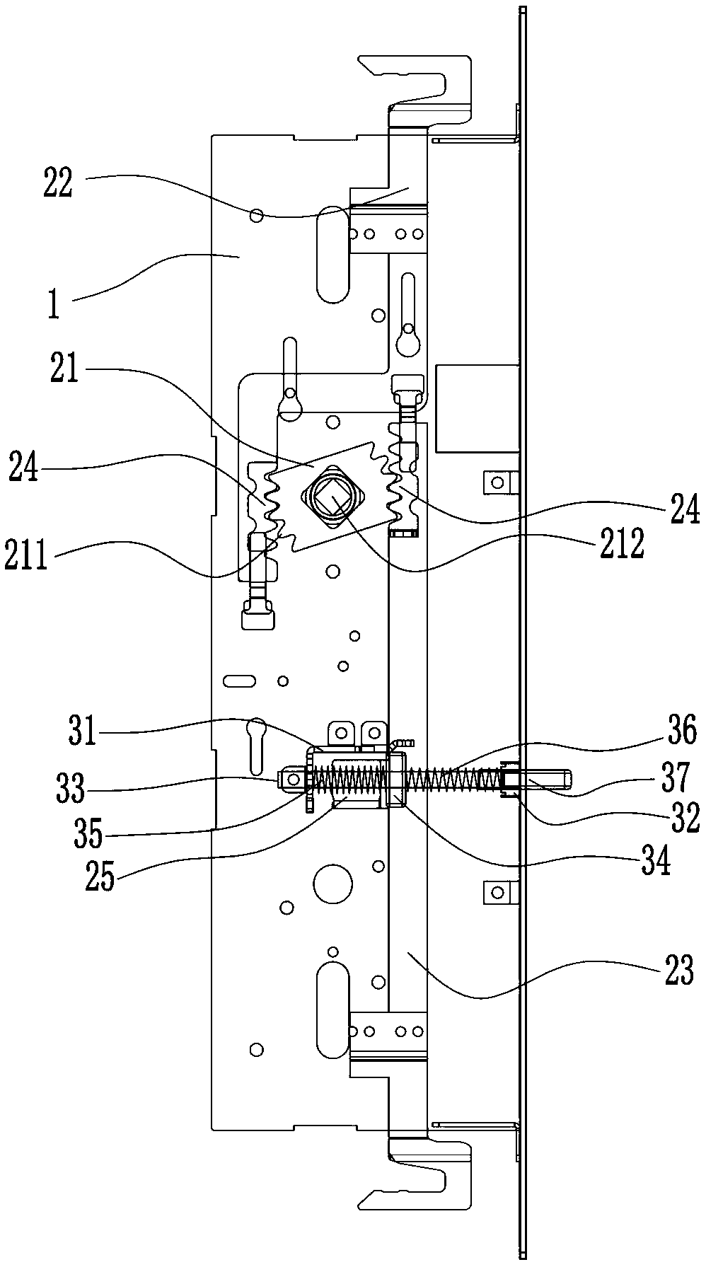
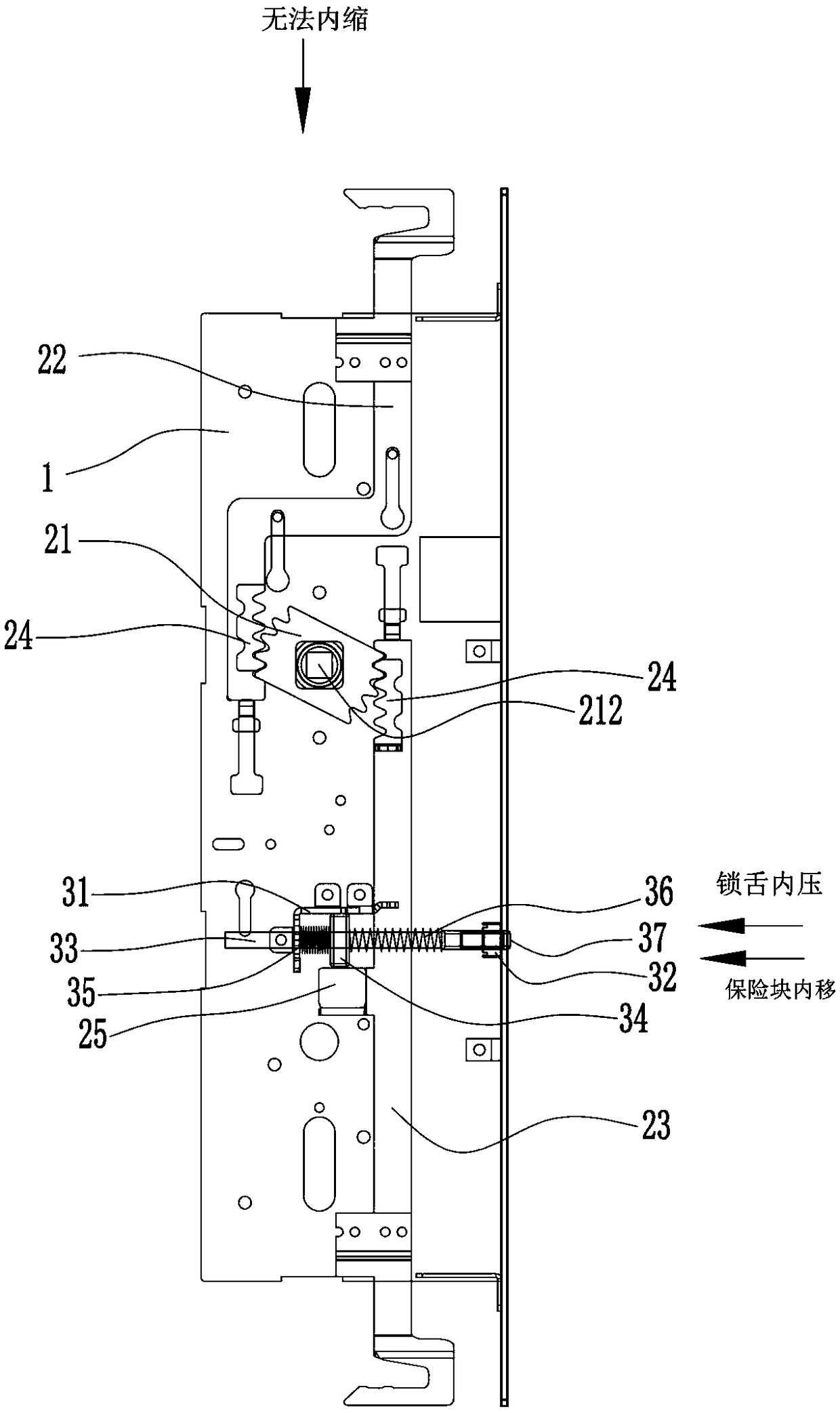
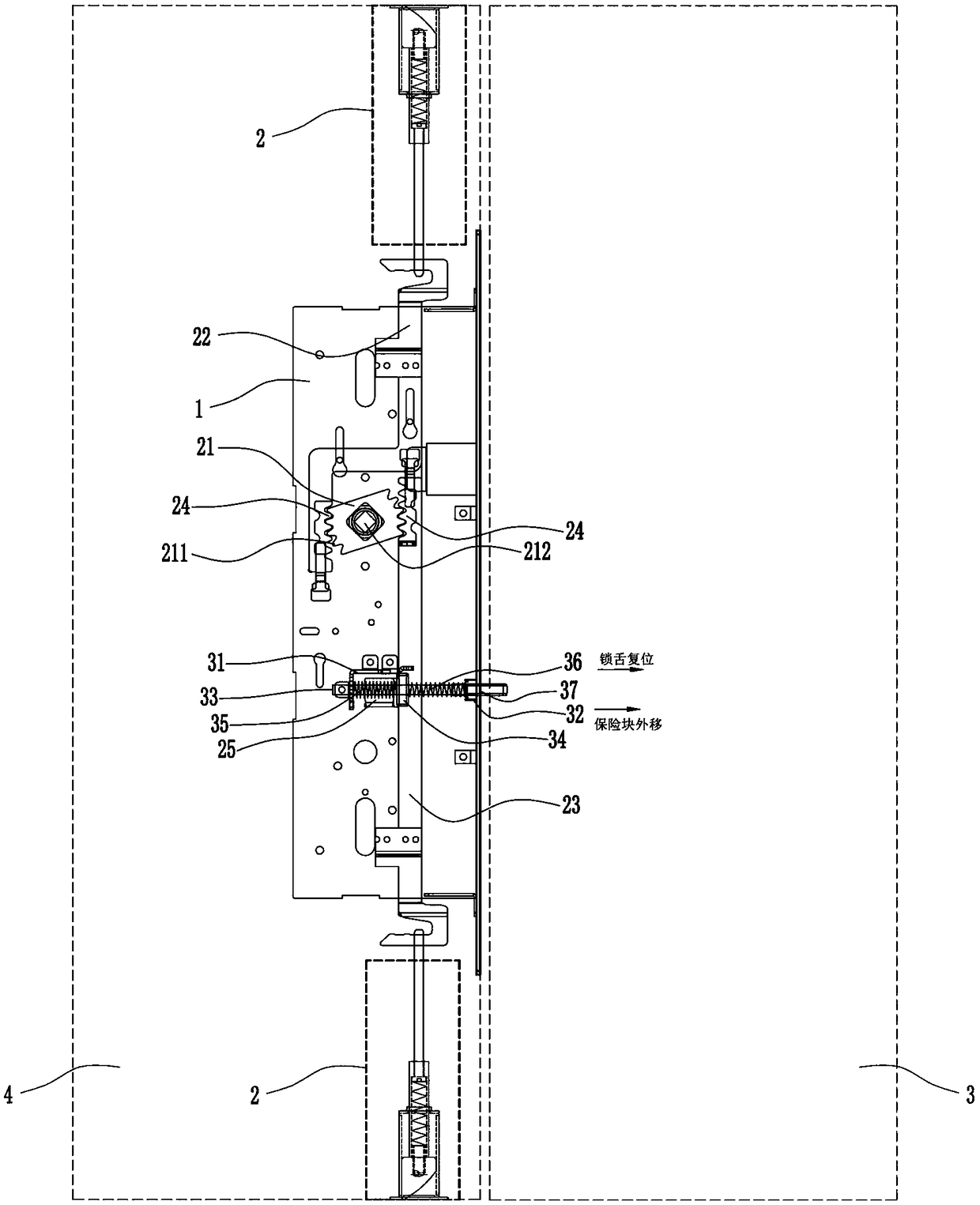
[0042] A secondary lock device such as Figure 1-Figure 2 As shown, it includes a housing 1, a telescopic assembly, and a safety elastic assembly; the telescopic assembly and the insurance elastic assembly are installed on the housing 1;
[0043] The telescopic assembly includes a secondary lock rotary piece 21, a transmission piece I22, and a transmission piece II23; the secondary lock rotary piece 21 is provided with teeth 211 and shaft holes 212; the transmission piece I22 and the transmission piece II23 are provided with a rack 24; the transmission piece II23 There is a block 25 on it, such as Figure 11 As shown; one end of the auxiliary lock rotating piece 21 is connected to the rack 24 on the transmission piece I22, and the other end is connected to the rack 24 on the transmission piece II23; the tooth 211 on the auxiliary lock turning piece 21 is connected to the transmission piece I22 and the transmission piece II23 The gear rack 24 on the upper part cooperates, and ...
Embodiment 2
[0050] A secondary lock device such as Figure 14 As shown, it includes a housing 1, a telescopic assembly, and a safety elastic assembly; the telescopic assembly and the insurance elastic assembly are installed on the housing 1;
[0051] The telescopic assembly includes a secondary lock rotary piece 21, a transmission piece I22, and a transmission piece II23; the secondary lock rotary piece 21 is provided with teeth 211 and shaft holes 212; the transmission piece I22 and the transmission piece II23 are provided with a rack 24; the transmission piece II23 There is a block 25 on it, such as Figure 11 As shown; one end of the auxiliary lock rotating piece 21 is connected to the rack 24 on the transmission piece I22, and the other end is connected to the rack 24 on the transmission piece II23; the tooth 211 on the auxiliary lock turning piece 21 is connected to the transmission piece I22 and the transmission piece II23 The gear rack 24 on the upper part cooperates, and under th...
Embodiment 3
[0059] A secondary lock device such as Image 6 , Figure 7 As shown, it includes a housing 1, a telescopic assembly, and a safety elastic assembly; the telescopic assembly and the insurance elastic assembly are installed on the housing 1;
[0060] The telescopic assembly includes a secondary lock rotary piece 21, a transmission piece I22, and a transmission piece II23; the secondary lock rotary piece 21 is provided with teeth 211 and shaft holes 212; the transmission piece I22 and the transmission piece II23 are provided with a rack 24; the transmission piece II23 There is a block 25 on it, such as Figure 11 As shown; one end of the auxiliary lock rotating piece 21 is connected to the rack 24 on the transmission piece I22, and the other end is connected to the rack 24 on the transmission piece II23; the tooth 211 on the auxiliary lock turning piece 21 is connected to the transmission piece I22 and the transmission piece II23 The gear rack 24 on the upper part cooperates, a...
PUM
 Abstract
Description
Claims
Application Information
 - R&D
- Intellectual Property
- Life Sciences
- Materials
- Tech Scout
- Unparalleled Data Quality
- Higher Quality Content
- 60% Fewer Hallucinations
Browse by: Latest US Patents, China's latest patents, Technical Efficacy Thesaurus, Application Domain, Technology Topic, Popular Technical Reports.
© 2025 PatSnap. All rights reserved.Legal|Privacy policy|Modern Slavery Act Transparency Statement|Sitemap|About US| Contact US: help@patsnap.com


