Warmer with self-cleaning function

A self-cleaning and heating technology, applied in chemical instruments and methods, household heating, space heating and ventilation details, etc., can solve problems such as embarrassment, unsatisfactory experience, affecting others' use, etc., to avoid odor overflow, Improve user experience and simple structure

Inactive Publication Date: 2019-03-08
桃江县益芳家用电器有限公司
0 Cites 1 Cited by

AI-Extracted Technical Summary

Problems solved by technology

[0002] The heater is a new type of heating equipment that has emerged in recent years. When in use, put your feet on the heater for heating. In order to ensure the heat preservation effect of the existing heater, the heater is generally set to open at the upper end and closed at...

Method used

As shown in Figure 1-7, the specific structure of the present invention is: a kind of heater with self-cleaning function, comprises the housing 1 that top is provided with opening, and described housing 1 interior is provided with heating device 2 ( The heating device 2 is preferably equipped with multiple switches inside the housing 1, each with a set of switches at each end to control the internal heating device 2 respectively. When there are few people, you can choose to open only one side. When there are many people, open both sides, which is more convenient to control and save power) , the heating device 2 includes a bracket 21 installed on the housing 1, the bracket 21 is oppositely provided with an insulating rod 22, and the insulating rod 22 is wound with a heating wire 23 (the heating wire 23 is preferably nickel Chrome wire, no bright light, dark fire heating, good heating effect, low cost), the heating wire 23 is used to generate heat after being connected to a power supply; a plurality of cylindrical footrests 3 are arranged at intervals in the housing 1, so The footrest 3 is located above the heating device 2, and its circumference is staggered with air inlets 301, and the inside is provided with air inlets 302 communicating with the air inlets 301, and the air inlets 302 are arranged inside the housing 1 The intake end pipeline of the air pump 7 is connected; the two ends of the pedal bar 3 are rotated and arranged on the U-shaped bracket 6, and the inner side of the U-shaped bracket 6 is provided with a cleaning strip 61 ( Water-absorbing materials such as sponges can be selected), the cleaning strip 61 and the liquid storage box 12 arranged on the outside of the housing 1 (the inside contains a mixed solution of sterilizing liquid, disinfectant, etc. cleaning) pipeline connection; the side of the housing 1 is relatively vertically provided with a card slot 104 that matches the two ends of the U-shaped bracket 6, and the card slot 104 is provided with a return position that presses the ...

Abstract

The invention discloses a warmer with a self-cleaning function. The warmer comprises a shell of which the top is provided with an opening, heating devices are arranged in the shell, and heating wiresare used for achieving heating after being connected with a power supply; multiple petal strips are arranged in the shell at intervals, air inlet holes are formed in the circumference of each petal strip in a staggered mode, the interior of each petal strip is provided with an air inlet channel communicating with the corresponding air inlet holes, and the air inlet channels are connected with an air inlet end pipeline of an air extracting pump arranged in the shell; the petal strips are arranged on U-shaped brackets, and cleaning strips are arranged on the inner sides of the U-shaped bracketsand connected with a pipeline of a liquid containing box; the side face of the shell is provided with clamping grooves, and return springs used for jacking the U-shaped brackets upwards are arranged in the clamping grooves; and a cavity is formed in the shell, a plasma deodorization device is arranged in the cavity, the air outlet end of the air extracting pump communicates with the cavity, and the side face of the lower portion of the cavity is provided with an air hole communicating with the interior of the shell. According to the warmer with the self-cleaning function, when the warmer is used, absorption treatment is conducted on bad smell of the foot soles, and peculiar smell overflowing is avoided.

Application Domain

Lighting and heating apparatusElectric heating system +3

Technology Topic

Electrical and Electronics engineeringFoot soles +2

Image

  • Warmer with self-cleaning function
  • Warmer with self-cleaning function
  • Warmer with self-cleaning function

Examples

  • Experimental program(1)

Example Embodiment

[0022] In order to enable those skilled in the art to better understand the technical solutions of the present invention, the present invention will be described in detail below with reference to the accompanying drawings. The description in this section is only exemplary and explanatory and should not have any limitation on the scope of protection of the present invention. .
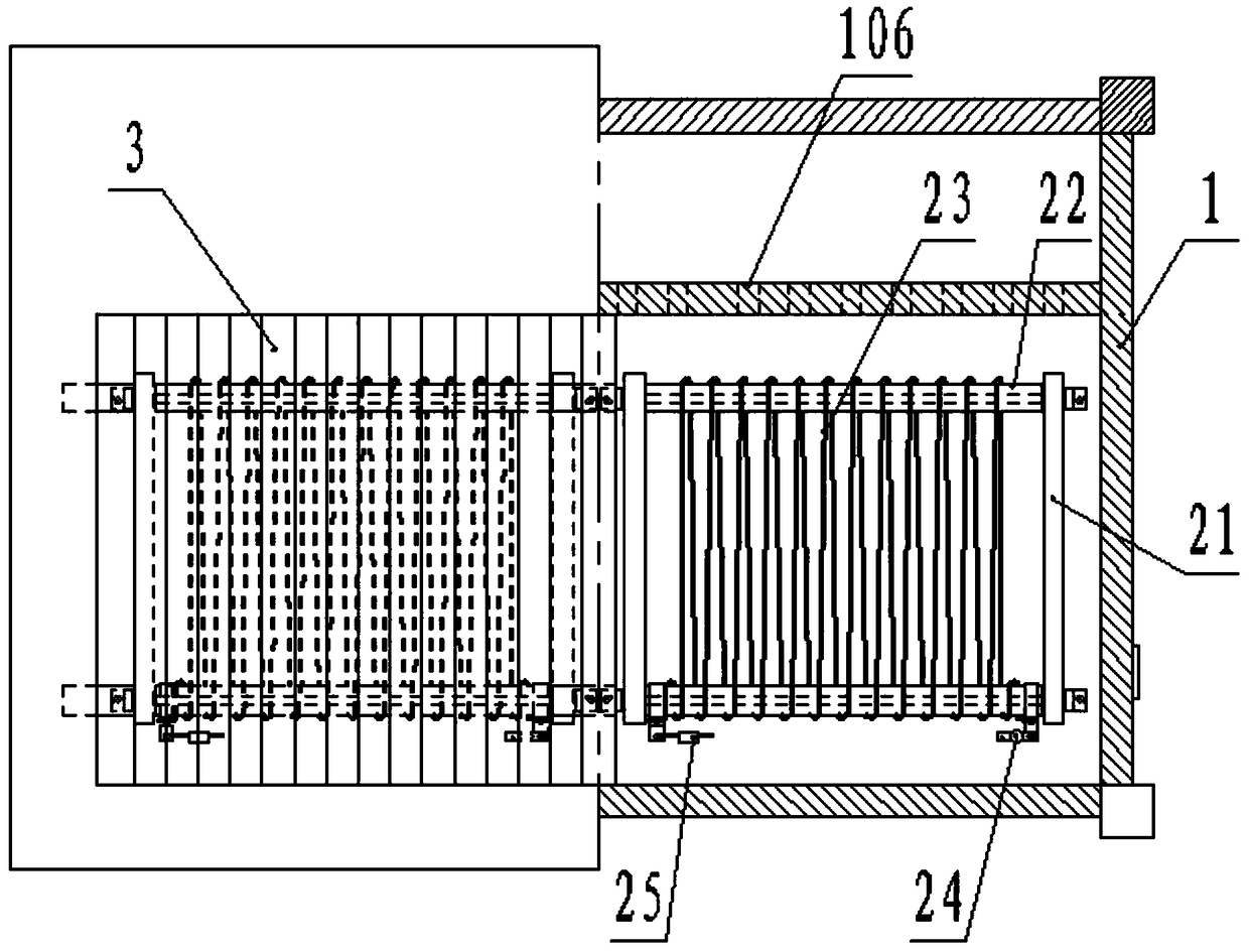
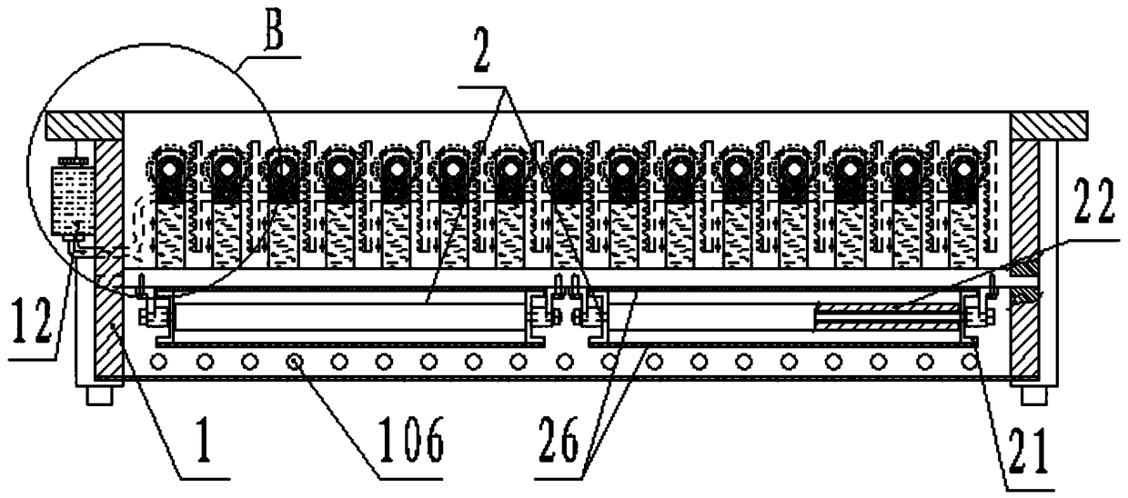
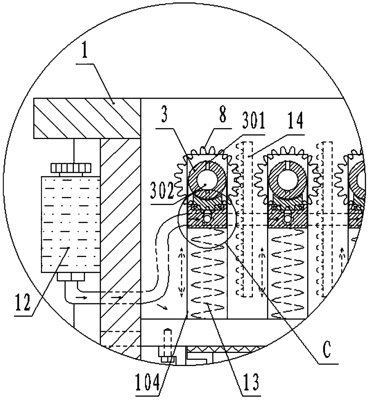
[0023] Such as Figure 1-7 As shown, the specific structure of the present invention is: a heater with a self-cleaning function, comprising a housing 1 with an opening at the top, and a heating device 2 inside the housing 1 (the heating device 2 is preferably a housing 1 There are multiple switches inside, each with a set of switches at both ends, respectively controlling the internal heating device 2. When there are few people, you can choose to open only one side, when there are many people, open both sides, which is more convenient to control and save power), the heating device 2 includes installation On the bracket 21 on the housing 1, an insulating rod 22 is opposite to the bracket 21, and a heating wire 23 is wound on the insulating rod 22 (the heating wire 23 is preferably a nickel-chromium wire, no bright light, dark fire Heating, the heating effect is good, the cost is low), the heating wire 23 is connected to the power source for heating; a plurality of cylindrical pedals 3 are arranged in the housing 1 at intervals, and the pedals 3 are located in the heating device 2 above, the air inlet 301 is staggered on the circumference, and the air inlet 302 communicating with the air inlet 301 is provided inside, and the air inlet 302 is connected to the air inlet end of the air pump 7 arranged inside the housing 1 Pipeline connection; the two ends of the footrest 3 are rotatably arranged on the U-shaped bracket 6, and the inside of the U-shaped bracket 6 is provided with a cleaning strip 61 that contacts the surface of the footrest 3 (water-absorbing materials such as sponges can be selected), The cleaning strip 61 is connected to a liquid container 12 (containing a mixture of sterilizing liquid, disinfectant, etc., used to clean the outer circumference of the pedal strip 3) arranged on the outside of the casing 1 in a pipeline; The side surface of the housing 1 is relatively vertically provided with clamping slots 104 that are matched with both ends of the U-shaped bracket 6, and the clamping slots 104 are provided with a return spring 13 (used to make the U-shaped The bracket 6 is on the upper part); the side of the slot 104 is provided with a rack 14, and one end of the foot bar 3 is sleeved with a gear 8 that matches the rack 14; the gear 8 is coaxial with the foot bar 3, and An elastic component 35 for restricting the rotation of the pedal strip 3 is provided inside; a closed cavity 105 is provided inside the housing 1, and a plasma deodorizing device 9 is provided inside the cavity 105, and the plasma deodorizing device 9 It includes an anode plate 91 and a cathode plate 92 arranged in parallel and spaced apart to generate a high-voltage plasma field for deodorization. The anode plate 91 is connected to the positive electrode of the high-voltage direct current power supply, and the cathode plate 92 is connected to the negative electrode of the high-voltage direct current power supply; the air pump 7 The air outlet end of the cavity 105 communicates with the cavity 105, and the side of the lower part of the cavity 105 is provided with an air hole 106 communicating with the inside of the housing 1.
[0024] Preferably, a recessed hole 303 is provided on the circumference of one end of the pedal bar 3, and the elastic component 35 includes a compression spring 351 and a steel ball 352, and the compression spring 351 is arranged in a counterbore 801 inside the gear 8. The steel ball 352 is matched with the concave hole 303.
[0025] Preferably, the U-shaped bracket 6 is provided with a bracket flow channel 601 inside, and the U-shaped bracket 6 is evenly provided with liquid outlet holes 602 for supplying cleaning liquid to the cleaning bar 61 along the axis direction of the footrest bar. The liquid outlet hole 602 communicates with the holder flow channel 601, and one side of the U-shaped holder 6 is connected to the liquid container 12 through the holder branch pipe 62 in a pipeline. The cleaning liquid is uniformly discharged from the liquid outlet 602 to the cleaning strip 61 after passing through the liquid container 12, the pipe, the support branch pipe 62, and the support flow channel 601 to clean the outer circumference of the footrest 3.
[0026] Preferably, one end of the footrest bar 3 is provided with a matching rotary joint 33 (to realize the conversion between pipe rotation and non-rotation connection), and the rotary joint 33 is connected to the air collecting pipe 34 through a hose. 34 is used to collect multiple gases from the inlet 302.
[0027] Preferably, a temperature control switch 24 is electrically connected to the loop of the heating wire 23 (the model may be KSD301). When the temperature of the heating device 2 reaches the set temperature, the temperature control switch 24 cuts off the power supply. When the temperature of the heating device 2 is lower than the set temperature, the temperature control switch 24 reconnects to the power supply and returns to a normal working state.
[0028] Preferably, a fuse 25 is electrically connected to the loop of the heating wire 23. It prevents that when the temperature control switch 24 on the heating device 2 is damaged and the power supply is not disconnected in time, after the fuse 25 is blown, the power supply is disconnected to play a protective role.
[0029] Preferably, a gear switch 4 (which is convenient for the user to set the temperature required for heating) and a power connection wire 5 are provided on the outside of the housing 1 electrically connected to the heating device 2. easy to use.
[0030] Preferably, a protective net 26 is provided on the top and bottom of the heating device 2. Prevent foreign matter from falling on the heating wire 23 and play a protective role.
[0031] Preferably, the passage formed by the anode plate 91 and the cathode plate 92 and the cavity 105 for gas passage is arranged in an S shape. The formation of gas flow is increased, and the treatment effect is better.
[0032] In specific use, when heating, the heating device 2 is turned on to start heating, and the user's foot is placed on the footrest 3 to warm up, and the odor from the user's foot passes through the air inlet 301, air inlet 302, and pipeline After the deodorizing treatment is performed by the suction pump 7, the cavity 105, and the plasma deodorizing device 9, it is discharged from the vent 106 on the side of the lower part of the cavity 105 into the heater to avoid the overflow of peculiar smell, improve the user experience effect and reduce the temperature At the same time, when the user steps on the pedal bar 3, the U-shaped bracket 6 moves down in the slot 104, the return spring 13 is compressed, and the gear 8 matches the rack 14, but due to foot friction The effect of force makes the pedal strip 3 not rotate, and the cleaning fluid reaches the cleaning strip 61 after passing through the liquid container 12 and the pipe. When the user leaves the pedal strip 3 when the user is not using it, the action of the return spring 13 When the U-shaped bracket 6 moves upward, the gear 8 and the rack 14 rotate together, and the gear 8 drives the pedal bar 3 to rotate at a certain angle (preferably 180 degrees) through the elastic component 35. At this time, the cleaning bar 61 is opposite to the pedal bar 3 Clean, sterilize, and disinfect the place just used to ensure that the outer surface of the footrest 3 is clean and does not affect the next use.
[0033] It should be noted that in this article, the terms "include", "include" or any other variants thereof are intended to cover non-exclusive inclusion, so that a process, method, article or device including a series of elements not only includes those elements, It also includes other elements not explicitly listed, or elements inherent to the process, method, article, or equipment.
[0034] Specific examples are used in this article to illustrate the principle and implementation of the present invention. The description of the above examples is only used to help understand the method and core idea of ​​the present invention. The above are only the preferred embodiments of the present invention. It should be pointed out that due to the limited expression of words, there are objectively infinite specific structures. For those of ordinary skill in the art, the principle of the present invention is not deviated from the premise Next, several improvements, modifications or changes can also be made, or the above technical features can be combined in an appropriate manner; these improvements, changes or combinations, or the concept and technical solution of the invention can be directly applied to other occasions without improvement , Should be regarded as the protection scope of the present invention.

PUM

no PUM

Description & Claims & Application Information

We can also present the details of the Description, Claims and Application information to help users get a comprehensive understanding of the technical details of the patent, such as background art, summary of invention, brief description of drawings, description of embodiments, and other original content. On the other hand, users can also determine the specific scope of protection of the technology through the list of claims; as well as understand the changes in the life cycle of the technology with the presentation of the patent timeline. Login to view more.

Similar technology patents

Method and system for controlling air conditioner

Owner:GD MIDEA AIR-CONDITIONING EQUIP CO LTD +1

Video photographing control device and method, and unmanned aerial vehicle

PendingCN106027896AImprove user experience
Owner:ZEROTECH (BEIJING) INTELLIGENCE TECH CO LTD

Automobile air conditioner control method, controller and automobile air conditioner control system

ActiveCN105857011AComfortable temperature inside the carImprove user experience
Owner:BEIJING CHANGAN AUTOMOBILE ENG TECH RES

Classification and recommendation of technical efficacy words

  • Improve user experience

Method, device and equipment for displaying multiple application windows on mobile terminal

InactiveCN102968243AImprove information acquisition efficiency and ease of operationImprove user experience
Owner:SHENZHEN YUNYINGGU TECH CO LTD

Content recommending method and device based on user characteristics

ActiveCN101957834AFacilitate the dissemination of informationImprove user experience
Owner:BAIDU ONLINE NETWORK TECH (BEIJIBG) CO LTD
Why Eureka
Try Eureka