Process cartridge regeneration method and regenerative process cartridge

A technology for processing boxes and waste toner bins, applied in electrography, optics, instruments, etc., which can solve problems such as waste, environmental pollution, and the inability of the drum 631 to receive transmission force, so as to facilitate regeneration, ensure printing quality, and regenerate Simple process and reliable effect

Inactive Publication Date: 2019-03-08
PRINT RITE UNICORN IMAGE PROD CO LTD
View PDF7 Cites 0 Cited by
  • Summary
  • Abstract
  • Description
  • Claims
  • Application Information

AI Technical Summary

Problems solved by technology

[0006] The rotational force receiving head 6322 of the process box 6 with the above structure adopts a ball-type universal joint driving connection structure. During transportation, the rotational force receiving head 6322 is easy to disengage, causing the drum 631 to fail to receive the transmission force, resultin

Method used


Image

  • Process cartridge regeneration method and regenerative process cartridge
  • Process cartridge regeneration method and regenerative process cartridge
  • Process cartridge regeneration method and regenerative process cartridge

Examples


no. 1 example

[0040] see Figure 5 , the regenerating method of the toner cartridge is composed of a dismantling step, a cutting step, a cleaning step, a refitting step and an assembling step.

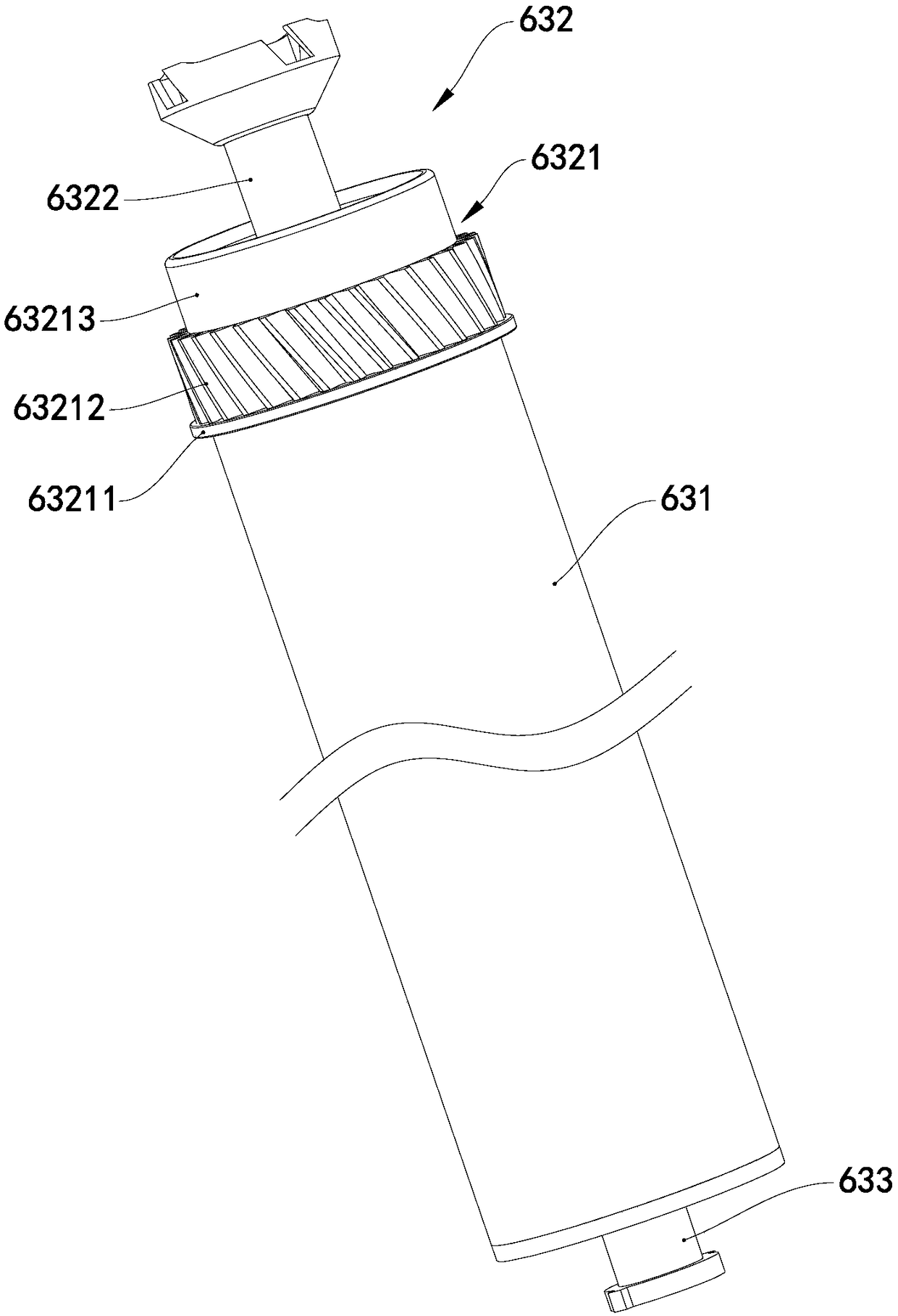
[0041] Disassembly steps: remove the connecting pins between the powder bin 61 and the waste toner bin 62, remove the powder outlet knife, magnetic roller and end cover from the powder bin 61, remove the photosensitive drum 63, the cleaning scraper and the charging roller.

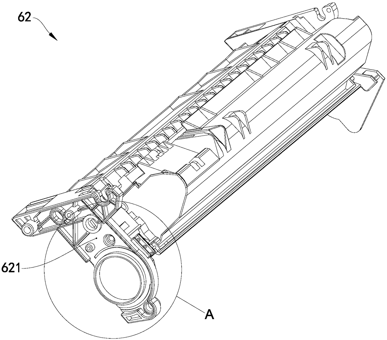
[0042] Cutting step: cut an opening 625 of the waste toner bin 62 at the same position in the axial direction of the supporting ring part 622 and the protruding ring part 623, cut the first slot 626 on the protruding ring part 623, and cut the reinforcing rib part 627 Out of the second slot 627. The waste toner bin 62 after the cutting step is as Figure 7 with 8 shown.

[0043] Cleaning step: cleaning the parts except the drum 631 and the rotational force transmission assembly 632 removed in the dismantling step and the wa...

no. 2 example

[0058] As a description of the second embodiment of the process cartridge reproducing method of the present invention, only the differences from the first embodiment of the process cartridge reproducing method will be described below.

[0059] see Figure 17 , The regeneration method of the process cartridge in this embodiment is composed of a disassembly step, a cleaning step, a refitting step and an assembly step. Wherein the disassembly steps are the same as the first embodiment of the regeneration method of the above-mentioned process cartridge, and only the different cleaning steps, refitting steps and assembling steps will be described below.

[0060] The cleaning step is to clean the parts removed in the dismantling step except the waste toner bin, the drum and the rotating force transmission assembly.

[0061] The refitting procedure is to use a structure that is the same as that of the dismantled waste powder bin, but the supporting ring part and the protruding ring ...


PUM


Abstract

The present invention provides a process cartridge regeneration method. The process cartridge comprises a waste toner box and a photosensitive drum; the photosensitive drum comprises a rotary force transfer assembly mounted on one axial end of the drum; a support ring portion is arranged on one end of the waste toner box, and a protruding ring portion protruding from the outer end surface of the waste toner box is formed in the axial direction of the support ring portion; and a reinforcing rib portion is formed on the outer end surface of the waste toner box near the protruding ring portion. The regeneration method comprises: a disassembling step; a cutting step of cutting an opening at the same axial position of the support ring portion and the protruding ring portion, cutting the first groove on the protruding ring portion, and cutting the second groove on the reinforcing rib portion; a modifying step of replacing a conventional rotary force transfer assembly with a new rotary forcetransfer assembly; and an assembly step of assembling the parts and filling the assembled parts with the toner to form a regenerative process cartridge. The regenerative process cartridge obtained byusing the regeneration method has good print quality and excellent re-regeneration performance. Further, the present invention also provides a regenerative process cartridge obtained by using the regeneration method.

Description

technical field [0001] The invention relates to a method for regenerating a process box and a regenerated process box obtained by using the method. Background technique [0002] An electrophotographic imaging device such as a laser printer is a device that uses the principle of electrophotography to form an image on a medium such as paper. It provides the toner required for printing through a toner cartridge; drum, and a developer roller that supplies toner onto the photosensitive drum to develop the electrostatic latent image. [0003] see figure 1 , an existing process box 6, comprising a waste toner bin 62, a photosensitive drum 63, a powder bin 61, a magnetic roller, a powder knife, a cleaning blade, a charging roller and an end cover, and the powder knife, a magnetic roller and an end cover are installed on the powder On the bin 61, the photosensitive drum 63, the cleaning blade and the charging roller are installed on the waste toner bin 62, and the toner bin 61 and ...

Claims


Application Information

Patent Timeline
IPC IPC(8): G03G21/18
CPCG03G21/181G03G21/1814
Inventor 杨晓锋丁文奕
Owner PRINT RITE UNICORN IMAGE PROD CO LTD
Why Eureka
Try Eureka