
MEMS microphone and electronic equipment applying same

A technology of microphone and sound input, which is applied in the field of sensors and can solve problems such as bad and easily damaged diaphragms

Pending Publication Date: 2019-03-08
WEIFANG GOERTEK MICROELECTRONICS CO LTD
View PDF0 Cites 6 Cited by
  • Summary
  • Abstract
  • Description
  • Claims
  • Application Information

AI Technical Summary

Problems solved by technology

At present, the MEMS chip with the diaphragm is directly corresponding to the sound hole on the circuit board, and the external airflow can directly pass through the sound hole to act on the diaphragm of the MEMS chip. When the external airflow is too large, it is easy to damage the diaphragm, resulting in defective

Method used


Image

  • MEMS microphone and electronic equipment applying same
  • MEMS microphone and electronic equipment applying same

Examples


Embodiment Construction

[0030] The following will clearly and completely describe the technical solutions in the embodiments of the present invention with reference to the accompanying drawings in the embodiments of the present invention. Obviously, the described embodiments are only part of the embodiments of the present invention, not all of them. Based on the embodiments of the present invention, all other embodiments obtained by persons of ordinary skill in the art without creative efforts fall within the protection scope of the present invention.

[0031] It should be noted that all directional indications (such as up, down, left, right, front, back...) in the embodiments of the present invention are only used to explain the relationship between the components in a certain posture (as shown in the accompanying drawings). Relative positional relationship, movement conditions, etc., if the specific posture changes, the directional indication will also change accordingly.

[0032] In addition, in t...


PUM


Abstract

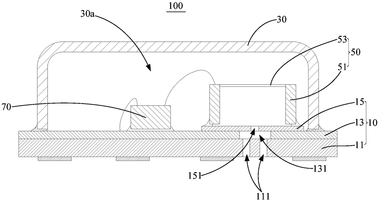
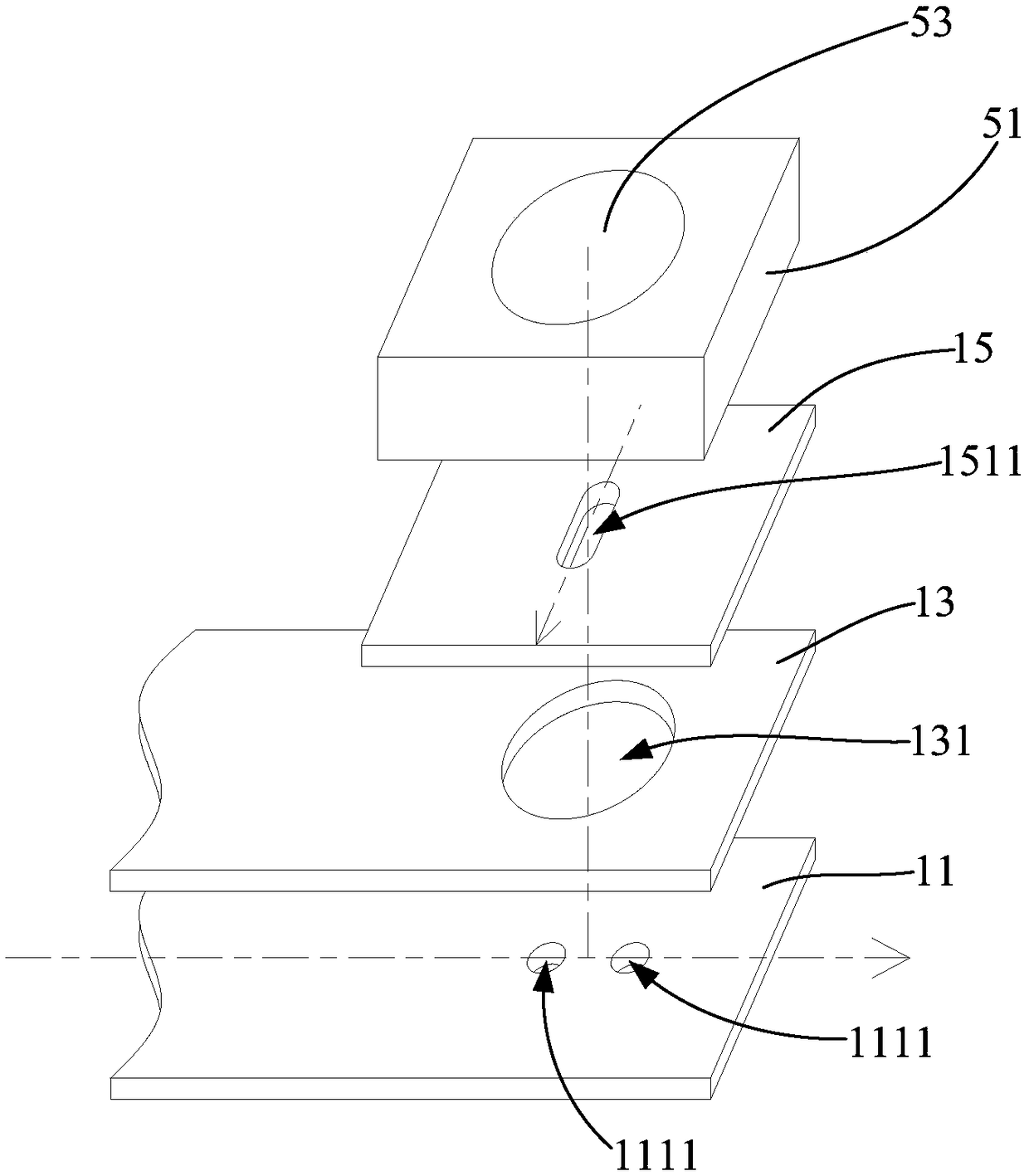
The invention discloses an MEMS microphone and electronic equipment applying the same. The MEMS microphone comprises an external packaging structure and an MEMS chip arranged in the external packagingstructure; the external packaging structure comprises a sound inlet for external sound waves to be input; an inlet layer, a buffer layer and a barrier layer which are sequentially stacked are arranged in a position, provided with the sound inlet, of the external packaging structure; a sound-transmitting hole is formed in the buffer layer; a first sound inlet structure penetrating through the inlet layer is arranged on the surface, facing the sound-transmitting hole, of the inlet layer; a second sound inlet structure penetrating through the barrier layer is arranged on the surface, facing thesound-transmitting hole, of the barrier layer; the first sound inlet structure extends in a first direction along the surface of the inlet layer; the second sound inlet structure extends in a second direction along the surface of the barrier layer; projection of the first sound inlet structure on the barrier layer and the second sound inlet structure are arranged in a crossed mode; the first soundinlet structure communicates with the outside; and the second sound inlet structure communicates with the MEMS chip. According to the technical scheme, a vibrating diaphragm of the MEMS chip can be prevented from being damaged due to over-large external air flow.

Description

technical field [0001] The invention relates to the technical field of sensors, in particular to a MEMS microphone and electronic equipment using the MEMS microphone. Background technique [0002] As a detection device, sensors are widely used in mobile phones, notebook computers, tablet computers and wearable devices. In recent years, with the rapid development of science and technology, Micro-Electro-Mechanical System (MEMS, Micro-Electro-Mechanical System) came into being, and MEMS microphone (an electric energy transducer made by micromachining technology) is one of them. It has the characteristics of small size, good frequency response characteristics, and low noise. At present, the MEMS chip with the diaphragm is set directly corresponding to the sound hole on the circuit board, and the external airflow can directly pass through the sound hole to act on the diaphragm of the MEMS chip. When the external airflow is too large, it is easy to damage the diaphragm, resultin...

Claims


Application Information

Patent Timeline
IPC IPC(8): H04R1/08H04R7/04
CPCH04R1/086H04R7/04
Inventor 庞胜利王顺衣明坤
Owner WEIFANG GOERTEK MICROELECTRONICS CO LTD
Learn More