Supercharge Your Innovation With Domain-Expert AI Agents!

Ball mill

A ball mill and tank technology, applied in the field of grinding equipment, can solve the problems affecting the use of the ball mill, low operation efficiency, waste of manpower, etc., and achieve the effects of saving physical strength, simple and convenient operation, and improving efficiency.

Inactive Publication Date: 2019-03-12
颍上县永军建材有限责任公司
View PDF8 Cites 2 Cited by
  • Summary
  • Abstract
  • Description
  • Claims
  • Application Information

AI Technical Summary

Problems solved by technology

[0003] The tank body of the ball mill will wear out after a long time of use, and needs to be repaired and replaced. However, the existing ball mill tank body and the fixing seat are generally connected by welding or bolts. Therefore, when the tank body needs to be disassembled, a large number of tools are required for cutting. Disassembly not only wastes manpower, but also has low operating efficiency, which affects the use of the ball mill

Method used


Image

  • Ball mill
  • Ball mill
  • Ball mill

Examples


Embodiment Construction

[0021] The following will clearly and completely describe the technical solutions in the embodiments of the present invention with reference to the accompanying drawings in the embodiments of the present invention. Obviously, the described embodiments are only some, not all, embodiments of the present invention. Based on the embodiments of the present invention, all other embodiments obtained by persons of ordinary skill in the art without making creative efforts belong to the protection scope of the present invention.

[0022] In the description of the present invention, it should be noted that the terms "center", "upper", "lower", "left", "right", "vertical", "horizontal", "inner", "outer" etc. The indicated orientation or positional relationship is based on the orientation or positional relationship shown in the drawings, and is only for the convenience of describing the present invention and simplifying the description, rather than indicating or implying that the referred d...


PUM


Abstract

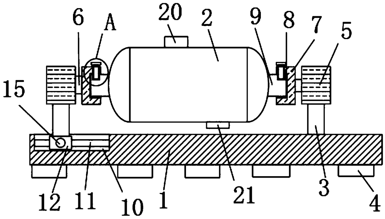
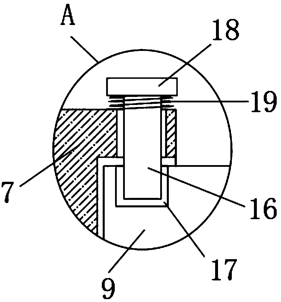
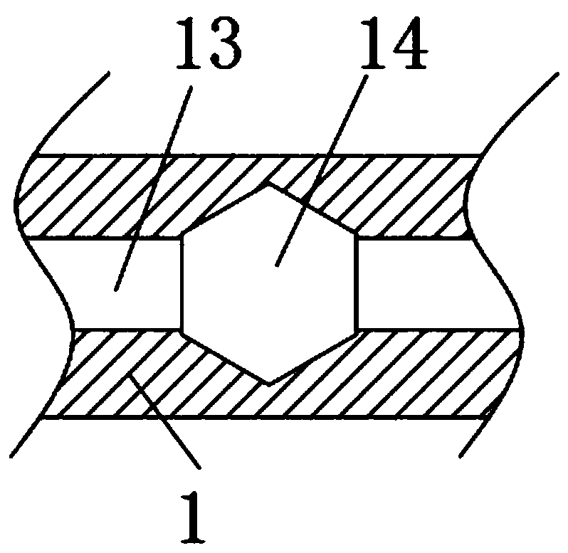
The invention discloses a ball mill. The ball mill comprises a base and a ball mill tank body; two supporting columns which are vertically and symmetrically arranged are fixedly connected to the sidewall of the upper end of the base, the ball mill tank body is arranged between the two supporting columns, each of side walls of one ends, away from the base, of the two supporting columns is fixedlyconnected with a motor, a driving end of each motor is rotationally connected with a rotating shaft which is transversely arranged, the side wall of one end, away from the corresponding motor, of eachrotating shaft is fixedly connected with a mounting block, clamping grooves are formed in the side walls of one sides, close to the ball mill tank body, of the two mounting blocks, clamping blocks are fixedly connected to the side walls of the two sides of the ball mill tank body, the two clamping blocks are inserted into the clamping grooves to be arranged, a mounting groove is formed in the side wall of the upper end of the base, and transversely-arranged supporting rods are fixedly connected to the inner walls of the two sides of the mounting groove. According to the ball mill, when the ball mill tank body is disassembled, a tool does not need to be used, the physical power is saved, and the disassembling and maintaining efficiency is improved.

Description

technical field [0001] The invention relates to the technical field of grinding equipment, in particular to a ball mill. Background technique [0002] The ball mill is a mechanical equipment that continues to crush ore or other materials after the crusher, aiming at obtaining finer particle products required by the process. The ball mill is widely used in the three major industries such as the mineral processing industry, the construction industry and the cement industry. The development of large industries has played a certain role in promoting. When the existing ball mill is working, the torque is transmitted to the large and small gears of the ball mill through the motor and the reducer, so that the cylinder of the ball mill rotates. Due to the rotation of the cylinder of the ball mill, the steel balls in the cylinder (if other grinding media) pass through the uneven The liner belt rises to a certain height, then falls freely, hits the material in the cylinder, and the g...

Claims


Application Information

Patent Timeline
IPC IPC(8): B02C17/10B02C17/18
CPCB02C17/10B02C17/18
Inventor 闫永军
Owner 颍上县永军建材有限责任公司
Features
  • R&D
  • Intellectual Property
  • Life Sciences
  • Materials
  • Tech Scout
  • Unparalleled Data Quality
  • Higher Quality Content
  • 60% Fewer Hallucinations
Learn More