Mold limiting device and sing method thereof

A technology of limiting device and mold, applied in the direction of forming tools, manufacturing tools, metal processing equipment, etc., can solve the problems of mold blade damage, upper mold and lower mold weight, shortening the service life of the mold, etc., to protect the mold and store it safely. Reliable and easy-to-use results

Inactive Publication Date: 2019-03-12
WUHU FEICHI AUTOMOTIVE COMPONENTS TECH
View PDF5 Cites 2 Cited by
  • Summary
  • Abstract
  • Description
  • Claims
  • Application Information

AI Technical Summary

Problems solved by technology

For some large molds, both the upper mold and the lower mold are very heavy. If the shadow and the mold closing stroke are not well controlled during the frequent mold opening and closing process, it is easy to cause damage to the mold edge; when the mold is not in use and stored, the upper and lower The molds are stored together, the mold core is easily damaged, and the service life of the mold is affected
[0003] At present, many molds have realized the integration of working limit and storage limit. The unreasonable storage position of the limit block caused damage to the mold, which brought great trouble to the mold designers. The inventor designed a limit device according to the actual production

Method used


Image

  • Mold limiting device and sing method thereof
  • Mold limiting device and sing method thereof
  • Mold limiting device and sing method thereof

Examples


Embodiment Construction

[0028] In the present invention, it should be understood that the terms "length", "width", "upper", "lower", "front", "rear", "left", "right", "vertical", "horizontal" ", "Top", "Bottom", "Inner", "Outer", "Clockwise", "Counterclockwise", "Axial", "Radial", "Circumferential" and other indications are based on The orientation or positional relationship shown in the drawings is only for the convenience of describing the present invention and simplifying the description, and does not indicate or imply that the referred device or element must have a specific orientation, be constructed and operated in a specific orientation, and therefore cannot be understood as Limitations on the Invention.

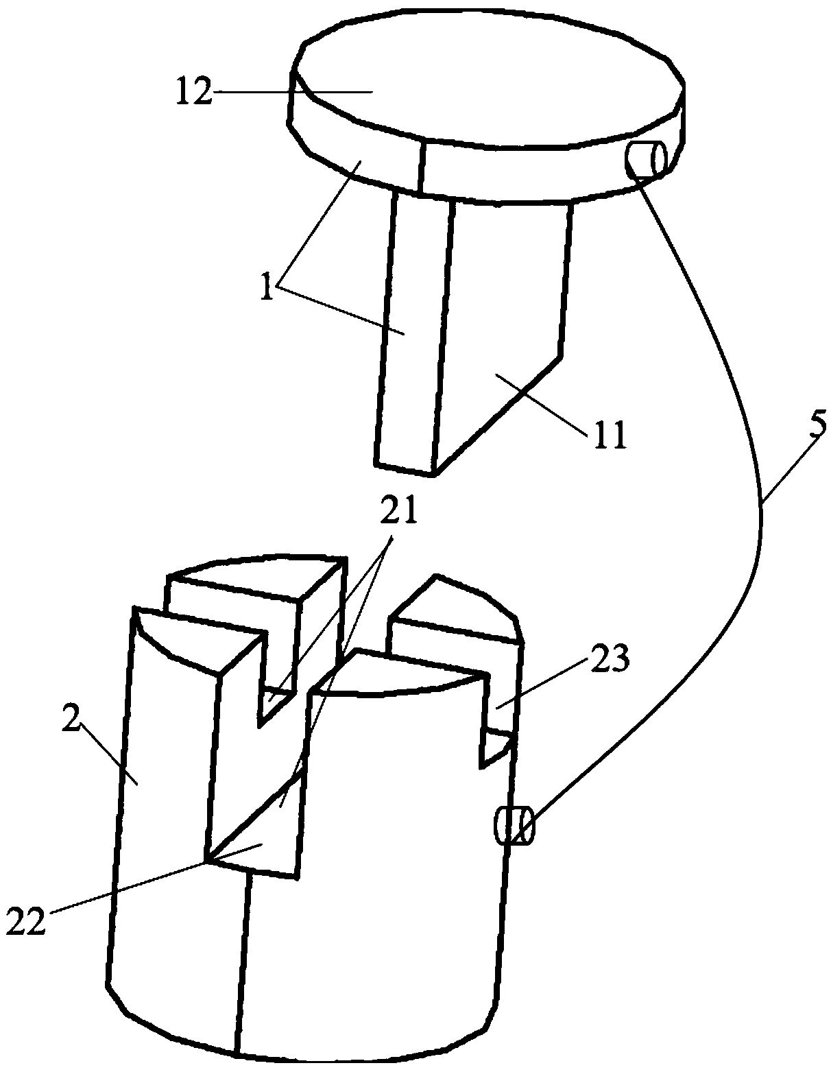
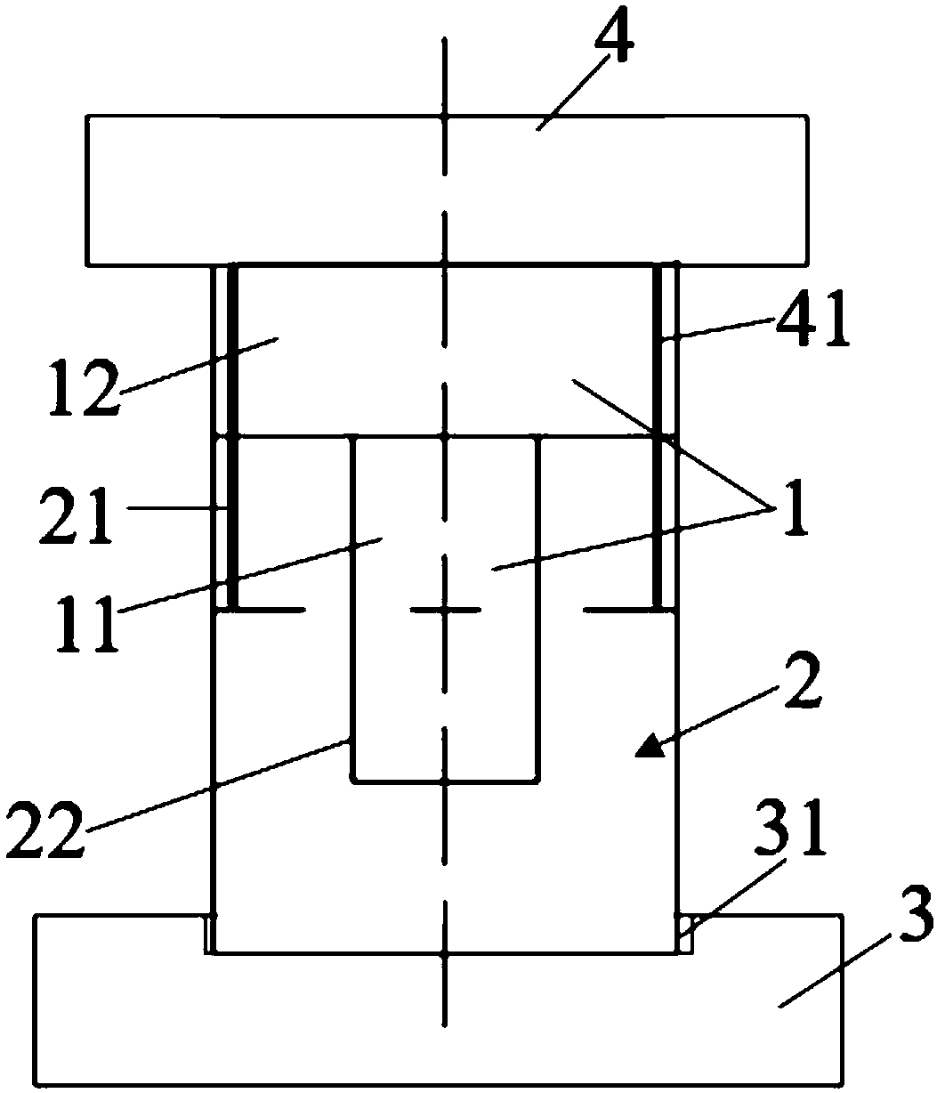
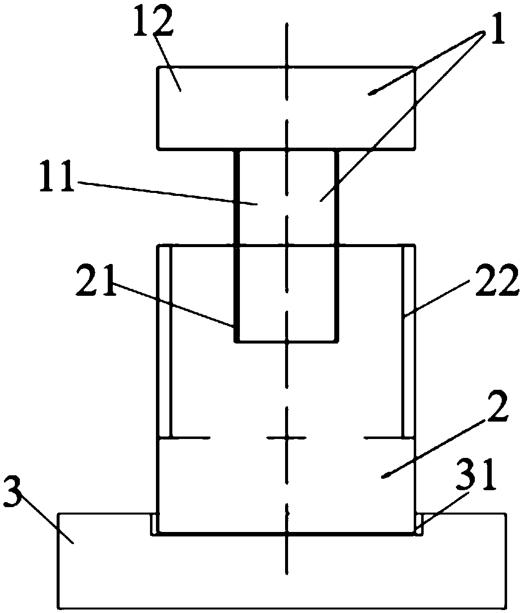
[0029] like figure 1 , figure 2 , image 3 As shown, a mold limiting device includes a limiting block 1 and a supporting column 2, the supporting column 2 is arranged on the lower mold 3, one end of the limiting block 1 cooperates with the supporting column 2, and the other end of the li...


PUM


Abstract

The invention discloses a mold limiting device. The mold limiting device comprises a limiting block and a supporting column; the supporting column is arranged on a lower mold; one end of the limitingblock is matched with the supporting column, and the other end of the limiting block makes contact with an upper mold; and the limiting block and the supporting column are made of magnets which are the same in magnetism. Through the principle that the like poles of the magnets repel, when a mold is opened, the limiting block automatically bounces away from the supporting column so that the purposethat the limiting device is automatically taken down can be achieved, and the situation that in the prior art, safety accidents occur due to the fact that an operator forgets to take down the limiting device is avoided. The invention further discloses a using method of the mold limiting device.

Description

technical field [0001] The invention belongs to the technical field of molds, and in particular relates to a mold limiting device and a using method thereof. Background technique [0002] The level of the mold directly reflects the industrial level of a country (or economy), and the stamping die is often used in the working limit and storage limit during use. For some large molds, both the upper mold and the lower mold are very heavy. If the shadow and the mold closing stroke are not well controlled during the frequent mold opening and closing process, it is easy to cause damage to the mold edge; when the mold is not in use and stored, the upper and lower If the molds are stored together, the mold core is easily damaged, which will affect the service life of the mold. [0003] At present, many molds have realized the integration of working limit and storage limit. The unreasonable storage position of the limit block causes damage to the mold, which brings great trouble to ...

Claims


Application Information

Patent Timeline
Patent Type & Authority Applications(China)
IPC IPC(8): B21D37/14
Inventor 李新建
Owner WUHU FEICHI AUTOMOTIVE COMPONENTS TECH
Why Eureka
Try Eureka