

Material boxing equipment and feeding device thereof
A material and material feeding technology, which is applied in the field of material packing equipment and its feeding device, can solve the problems of low overall efficiency, low efficiency, and difficult transfer and flow
- Summary
- Abstract
- Description
- Claims
- Application Information
AI Technical Summary
Problems solved by technology
Method used
Image

Examples
Embodiment
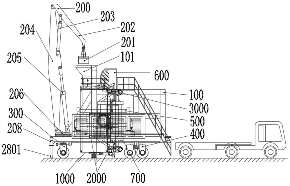
[0094] Such as Figure 1-Figure 10 As shown, a material feeding device described in this embodiment includes a feeding frame 100 for carrying a container 1000, a feeding guide funnel 101 is installed on the feeding frame 100, and a batch type bulk material is conveyed to The feeding conveying mechanism 200 at the blanking guide funnel 101, the distance between the position where the blanking guide funnel 101 is installed and the ground is greater than the length of the container 1000 to be loaded, based on this structure, a control room 600 can be set on the loading frame and stairs to the control room.
[0095] In this embodiment, a driving wheel assembly is installed on the bottom of the feeding frame 100, and the driving wheel assembly includes a steering wheel assembly 300 and a driving wheel assembly 400, and the steering wheel assembly 300 and the driving wheel assembly 400 are respectively installed on the feeding frame 100 at both ends of the bottom surface; furthermo...
Embodiment 2
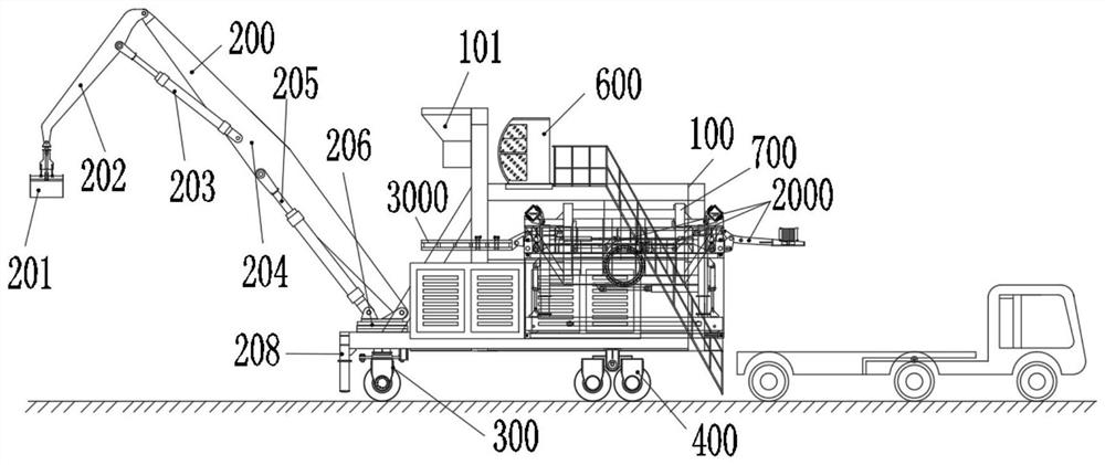
[0100] Such as Figure 7 and Figure 8 As shown, the general structure of the material feeding device described in this embodiment is consistent with that of embodiment 1, but it is different from embodiment 1 in that it also includes a bucket wheel for conveying bulk materials to the material conveying mechanism. Material mechanism 803, the feeding part of material conveying mechanism 200 is rotatably installed on bucket wheel retrieving mechanism 803, and the opening of hopper 804 on bucket wheel retrieving mechanism 803 corresponds to the conveying parts of material conveying mechanism, bucket wheel retrieving mechanism 803 It is a bulk cargo reclaiming component, which is composed of a rotating bucket wheel body, a rotating drive deceleration mechanism and a power source (electric motor or hydraulic motor). , and during the rotation of the bucket wheel, the hopper discharges after retrieving the material, and the discharged material directly enters the conveying part of t...
Embodiment 3
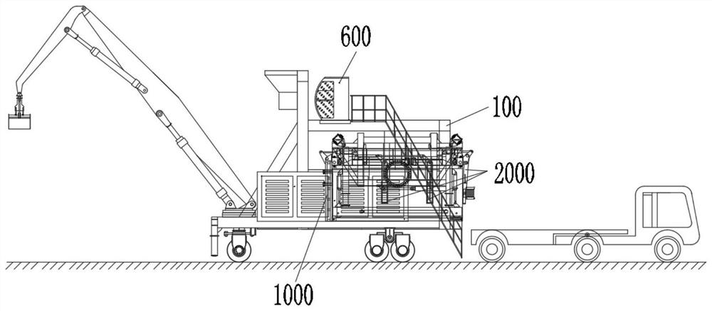
[0105] Such as Figure 9 and Figure 10 As shown, a material feeding device described in this embodiment has a general structure consistent with that of Embodiment 1, but is different from Embodiment 1 in that: the material conveying mechanism 200 includes a frame 704 and a conveyor belt with corrugated sidewalls. In the second belt conveying mechanism, one end of the frame 704 is placed on the ground, and the other end abuts against the blanking guide funnel 101; the second belt conveying mechanism includes an upper transverse conveying part 703, an intermediate conveying part 702 and a lower transverse conveying part 701, The upper transverse conveying part 703 and the lower transverse conveying part 701 are respectively placed on the top and bottom of the frame 704, the middle conveying part 702 is placed in the middle of the frame 704, and the upper transverse conveying part 703 is docked with the feeding port of the blanking guide funnel 101 , the support column 901 and ...
PUM
 Abstract
Description
Claims
Application Information